Summary of Portable Bluetooth-enabled scrolling LED matrix display- Part 1
This article details a portable, Bluetooth-controlled 8×64 monochromatic LED matrix designed for scrolling text at home parties. Controlled by an Arduino and using an HC-06 module to receive data from a smartphone app, the display consists of eight daisy-chained 8×8 modules. The project features a custom enclosure made from furring strip boards and utilizes MAX7219 driver chips on each module for efficient cascading.
Parts used in the Portable Bluetooth-enabled scrolling LED matrix display:
- Eight 8x8 monochromatic LED matrix modules with MAX7219 driver chip
- Arduino microcontroller
- HC-06 Slave Bluetooth transceiver module
- Bluetooth SPP Pro Android application
- Furring strip boards for enclosure construction
- 5-pin angled male header (J1)
- 5-pin angled female header (J2)
- Two 1x8 straight female headers
- Four 3.5 mm mounting holes
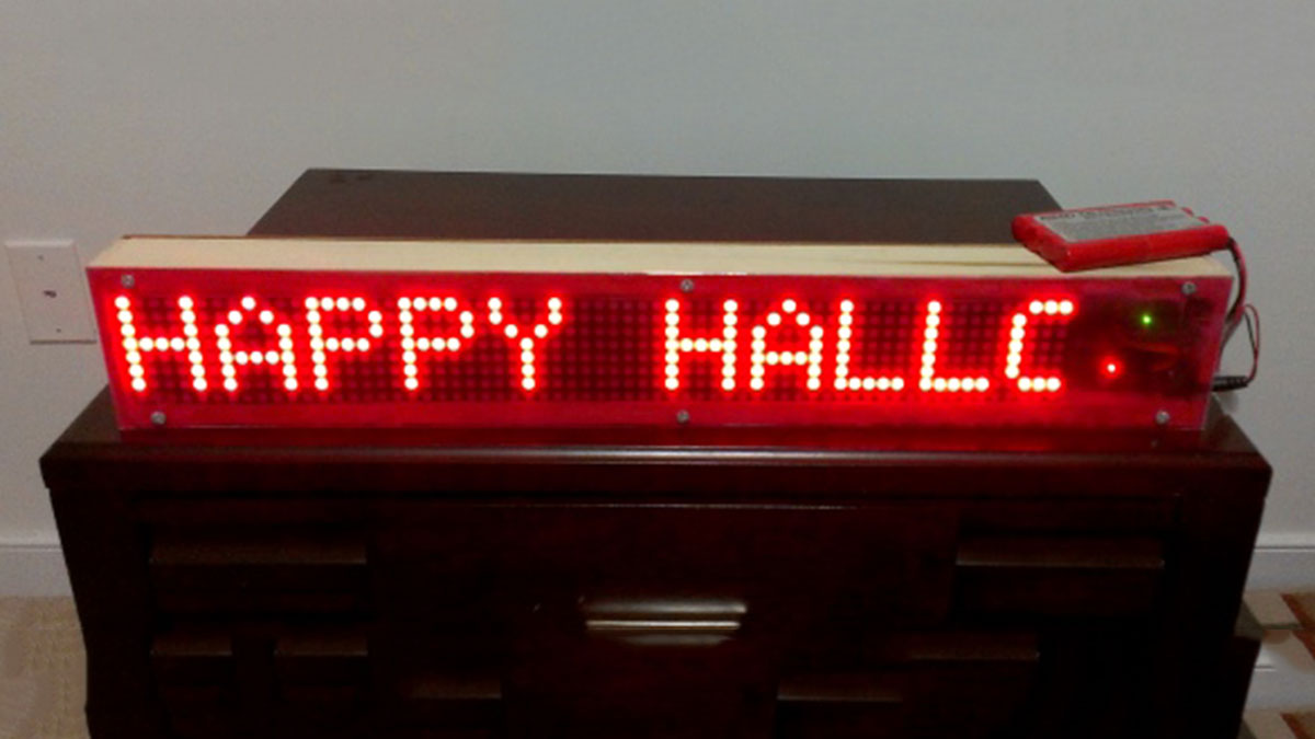
LED matrix displays are great fun. They are visually charming, and readable from a far viewing distance with a much wider angle of view as compared to many other types of electronics displays. They can display all kinds of information, including text, graphics, and animation. This project is about making a portable Bluetooth-controlled 8×64 monochromatic LED matrix (total 512 LEDs) for displaying scrolling text message. I made this display to use at home parties or other occasions for displaying greeting messages. The text data to be displayed can be sent from a smartphone using the Bluetooth connection. The display is Arduino-controlled and uses the HC-06 Slave Bluetooth transceiver module for receiving data from the smartphone. I am also using the Bluetooth SPP Pro (freely downloadable) App (developed by Jerry.Li) on my HTC One Android smartphone for sending text message to the matrix display. The complete project has got a nice enclosure made by myself using furring strip boards bought from the Home Depot. We looked at a similar project earlier made by Jollyfactory, who used bi-color LED matrices, which required two MAX7219 devices per 8×8 matrix.
Hardware design
This project uses eight pieces of 60.5mm x 60.5mm (2.4″ x 2.4″) monochromatic 8×8 LED matrix modules with A-type polarity, which means the rows are common-anodes and the columns are common-cathodes. The total size of the display area thus becomes about 2.4″ x 19″ (60.5mm x 483mm). Making one big piece of PCB of that size usually costs more than making small and cascadable modules. So I designed 8×8 LED matrix modules and daisy-chained eight of them to make the 8 rows x 64 columns matrix required for this project. Each module consists of an 8×8 monochromatic LED dot matrix display with onboard MAX7219 driver chip. I have named this module Easy Matrix. It consists of a 5-pin angled male header (J1) on the right side and a 5-pin angled female header (J2) on the left side of the board. Both the headers are precisely aligned along horizontal so that the male header of one module gets easily plugged onto the female header of second module, and so on. Two 1×8 straight female headers are used as sockets to hold the LED matrix module. One of the header socket is marked with a “circle with 1” to indicate where the pin number 1 of the LED matrix display should be inserted. Four 3.5 mm mounting holes are also available at four corners of the PCB. The MAX7219 data and control signals are fed from the J1 header of the first module (the right-most module) in the chain. The complete schematic and board files can be downloaded from a link provided at the end of this section. Here are some pictures of an Easy Matrix module below.
For more detail: Portable Bluetooth-enabled scrolling LED matrix display- Part 1
- What is the primary purpose of this project?
The display is designed for use at home parties or other occasions to show greeting messages. - How does the device receive text data?
Data is sent from a smartphone via a Bluetooth connection using an HC-06 Slave Bluetooth transceiver module. - Which application is used to send messages to the display?
The user employs the Bluetooth SPP Pro app developed by Jerry.Li on an HTC One Android smartphone. - How many LEDs are included in the total matrix?
The display contains a total of 512 LEDs arranged in an 8×64 configuration. - What is the physical size of the display area?
The total size of the display area is approximately 2.4 inches by 19 inches. - Why were small modules chosen over a single large PCB?
Creating one large PCB of that size usually costs more than making small and cascadable modules. - How are the individual modules connected together?
The modules are daisy-chained by plugging the male header of one module onto the female header of the next. - What polarity type do the LED matrix modules have?
The modules use A-type polarity where rows are common-anodes and columns are common-cathodes.