Summary of Pneumatic Inverted Pendulum
This project builds a pneumatic inverted pendulum: a cart driven by an air cylinder (proportional valve control) carries a 360° pendulum attached to a rotational encoder; a linear encoder measures cart position. Arduino reads both encoders, computes a control voltage, and sends it through a DAC0808 and LM324 amplifier to drive the proportional valve. Shared grounds are required for supplies; the flow control valve is unused. Encoders provide quadrature A/B signals; counts convert to radians and meters for angle and position calculations.
Parts used in the Pneumatic Inverted Pendulum:
- Air compressor
- Proportional valve
- Air cylinder (pneumatic actuator)
- Cart (aluminum box)
- Carrier (guide for cart)
- Rotational encoder S1-1250-250-I-N-D
- Pendulum (attached to encoder shaft)
- Linear encoder (black box with internal rotational encoder)
- Arduino (data acquisition and control)
- Digital-to-Analog Converter DAC0808
- Operational amplifier LM324
- +12V and -12V power supplies (for op amp)
- Wiring and common ground connections
Construction
Mechanical structure
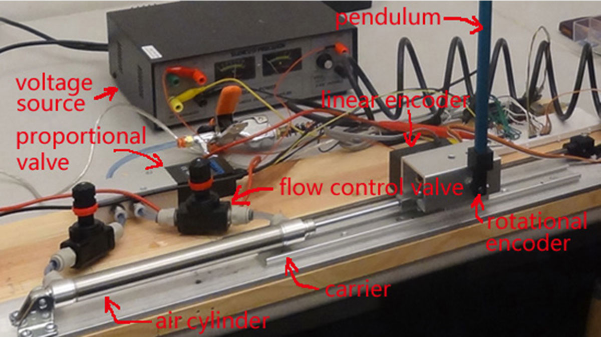
Note: the flow control valve is unused.
Control circuit board
Note that the “black green red yellow” in linear encoder diagram are just merely the color of wires. You might have different ones, but after watching VIDEO 3, it should be clear on how to use a linear encoder–the connection and programming are similar to rotational encoder. The operational amplifier should be connected to the +12 and -12 power supplies (not depicted). As noted above, if using separate power supplies, they must share a common ground.
Arduino
Visit arduino.cc to learn more.
Rotational encoder
The rotational encoder used in this project is S1-1250-250-I-N-D (more detail available in TABLE 1).
This encoder has 1250 counts per 360 degree (2*pi radians). Therefore, we have:
How to read an encoder:
When you rotate the encoder’s shaft, there will be signals from Channels A and B. Channels A and B are square waves with the same amplitude and frequency, but offset by 90 degrees. Note that when rotating in a different direction at the rising edge of channel A, channel B signal will be different–say, if rotating clockwise results a low valve of channel B at the rising edge of channel A; then when rotating counterclockwise, at the rising edge of channel A, channel B will give a high valve.
Linear encoder
Inside the black box of the linear encoder, there is a rotational encoder. The black box travels along a track. Therefore, linear encoder and rotational encoder are the same thing–there are also channel A and B in linear encoder, and their signals are the same as rotational encoder. The stroke of air cylinder is 0.1512m, and the linear encoder results 2993 counts travelling that distance. So, we have:
Digital-analog converter and operational amplifier
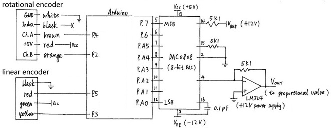
The DAC in used is DAC0808, and the operational amplifier in used is LM324. Basically what Digital Analog Converter (DAC) does is: given a digital signal from Arduino, DAC outputs an analog signal, which is used to control proportional valve. But because the DAC’s output is current and has very little power, we need an amplifier to drive the proportional valve. DAC0808 is an 8-bit DAC, and we give VREF = 12V. If we want a 6.6V output, here is how to calculate the digital value for it:
For more detail: Pneumatic Inverted Pendulum
- How does compressed air reach the air cylinder?
Compressed air from the air compressor goes into the proportional valve, which outputs two air branches that connect to the air cylinder. - Can the pendulum rotate fully?
Yes, the pendulum is attached to the encoder shaft and is able to rotate 360 degrees. - What encoders are used to measure angle and position?
A rotational encoder (S1-1250-250-I-N-D) measures angle and a linear encoder (which contains a rotational encoder inside) measures cart position. - How are encoder counts converted to physical units?
Rotational encoder: alpha = 0.00503 * angle_count (radians). Linear encoder: x_c = 0.0000505 * pos_count (meters). - How is the proportional valve controlled electrically?
Arduino calculates an output voltage, sends digital data to DAC0808, and the DAC output is amplified by LM324 to drive the proportional valve. - Does the project use the flow control valve?
No, the flow control valve is unused. - How are encoder signals read regarding direction?
Channels A and B produce quadrature square waves; the relative state at channel A rising edge indicates rotation direction via channel B level. - What power supplies are required for the operational amplifier?
The LM324 op amp should be connected to +12V and -12V power supplies, and all supplies must share a common ground if separate.