In the second project in my pick to light, I am using WIFI to pass the data between PC and Arduino.
Things used in this project
Story
This is the second project in my pick to light exploration. In the first, I outlined how I see a simple pick to light working and I created a simple pick to light using serial communication (Please read this if you wish to understand more of what I am doing here).
It worked but was tethered to the PC by the cable. In this project I want to develop the process using Wi-Fi and additionally I want to include the sequence number in the picking confirmation so that if anything goes wrong the system knows where the worker has picked up to. I am going to use an MKR1000 in the same way as I did in project 1 but communicate using WiFi. To do this I am going to use UDP (User Datagram Protocol ). Though I have never used this before, thanks to the libraries in Arduino and Python, this proved relatively easy to create.
The following steps are broadly similar to project 1 so if you have followed that then you will be already familiar with some of the steps and they won’t need to be repeated.
Step 1
To get started we need to have Python v 3.6 or greater on our laptop or pc. You can download that from here:
https://www.python.org/downloads/
Step 2
This time we will use the Python socket library for communicating and it is already installed so nothing needs doing to make UDP work.
Step 3
We also need the Arduino IDE either the PC version or the Web version. These can be downloaded here:
https://www.arduino.cc/en/Main/Software
or connected to here:
The instructions on the site are comprehensive so I won’t duplicate them unnecessarily.
Step 4
Launch the Python IDLE on your PC or Laptop and type: import os press: enter.
Then type: os.getcwd() this should give you your current working directory (cwd).
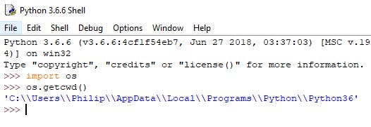
Python working directory
Step 5
In Notepad I created a comma separated value file and it quite simply contains a sequence number formatted to always be 4 digits and a bin number separated by a comma. See Notepad screen shot below and also text file attached which you can download. I saved this as sequence1.txt in the cwd that we gathered in step 4 (you can save the file with the extension of csv but it isn’t necessary for the csv to work). Saving the file to the cwd simplifies things when we come to read in the file with the python script as we won’t have to specify a location where the file is stored because it will automatically look in the cwd.
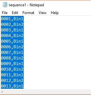
txt file containing csv sequence
Step 6
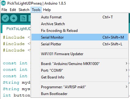
We will use serial in the Arduino sketch but only so we can see the printed messages on the serial monitor.
Step 7
The Python script needs to read in the content of the csv file one line at a time and send the sequence number and the Bin number across the UDP connection and then wait until the Arduino returns acknowledgement, which is the sequence number of the last bin number, to say that the part is picked. If the sequence number received does not match the last sequence number sent, the Python program will stop with an error message indicating the sequence number. This will enable the sequence to be restarted at the correct place. I have added comments to the script so you can understand what I have written.
Copy the script and then launch the IDLE and then >File >New File and paste the script into the window. Then >File >Save As give it a name (it doesn’t matter what you call it as long as you know the name).
Step 8
The Arduino sketch needs to connect to the internet then wait to receive the udp data from the PC for the next pick. It then acts on what it receives by lighting the LED that matches the bin in the sequence. It then needs to monitor the button that represents that bin to see if it is pressed. Once the worker presses the button to say the part is picked the sketch turns out the LED and sends a message containing the last sequence number back to the PC or Laptop to say the part was picked. It then then waits to receive the details for the next pick.
So if you are using the Arduino web editor copy from below the sketch and in the Arduino Web Editor select >sketchbook >NEW SKETCH
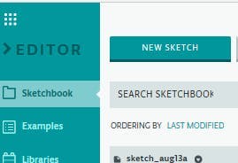
Arduino Web Editor
Then paste the script in the new sketch completely replacing everything that is in there.
If you are using the Arduino web editor as soon as you paste in the sketch the editor identifies the need to create a secret file which will contain the SSID and password for that server.

It is just a simple case of adding the relevant details to the file in the spaces provided.
With Arduino IDE it may be just as easy but if it is I couldn’t find it. However, because I started my sketch with the example sketch WiFiUdpSendReceiveString.
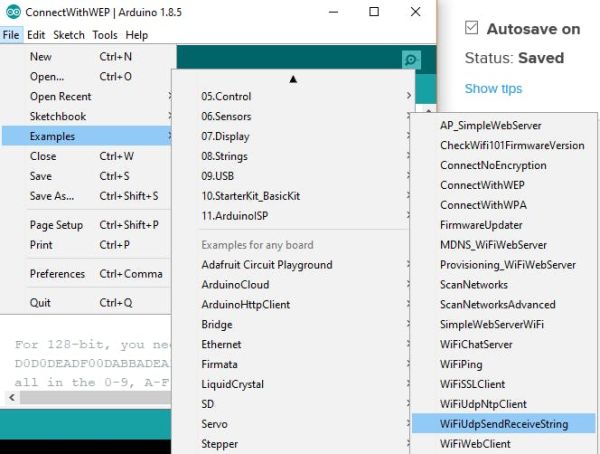
If you open this you will find a tab arduino_secrets.h already inside it. Add your SSID and password then paste the sketch below over the sketch already there and save as any name you like.
If you are using the Arduino IDE you will need to include the library WiFi101 the following link explains how to add a library if you don’t know.
https://www.arduino.cc/en/Guide/Libraries
Download to the MKR1000.
Step 9
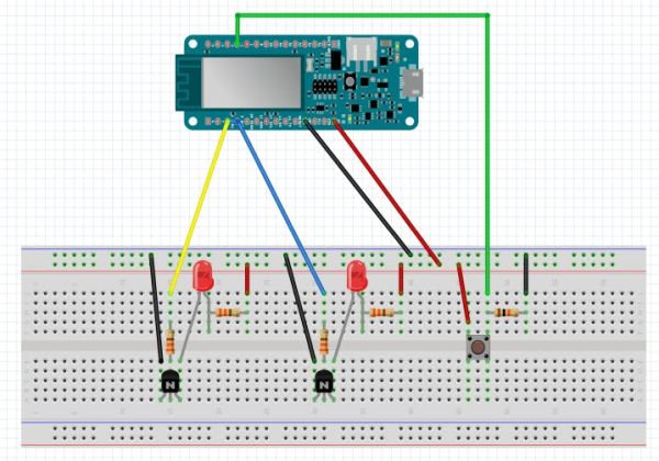
Connect everything up as per the fritzing diagram. If you have followed project 1 then you will see that I have wired this differently. The reason behind this is that as soon as the WiFi on the MKR1000 becomes active for some reason the power drops across pins 8 and 9 and the LEDs won’t illuminate. I couldn’t find anyone else on the web posting anything about this problem so I used the transistor to get round it. I’m sure there will be an explanation for this but so far I haven’t found it.
Warning! Please make sure that the resistors you use are suitable for the LED and the NPN transistor you use. Also be certain that you wire this up correctly as allowing the 5V to short across the pins 8 and 9 could destroy your Arduino. Use a diode if you are unsure.
Step 10
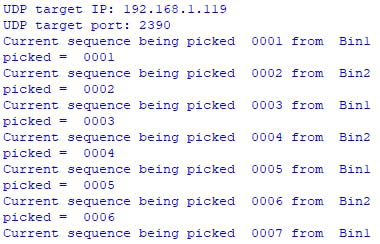
Check the Arduino has connected to the server and then run the Python script using F5 and the LED that represents Bin1 will light up. Pressing the button to confirm the part has been picked will send the sequence number back to the Python program where it will be checked and if correct, the next sequence is sent.
The Python output will look like this
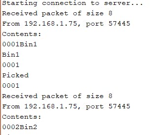
The serial monitor output will look like this:
You can test the sequence failure by commenting the line:
myseq.toCharArray(ReplyBuffer, 5);
and uncommenting the line:
//char ReplyBuffer[5] = “0001”;
as follows;
When you run the python program now the execution will stop after the second bin as it will report the sequence number of the first bin.

In the event of a sequence failure the person creating the sequence would need to edit the file containing the sequence and restart the arduino and the Python program.
Conclusion
Well I think I have achieved what I set out to do. It is simple and would be easy to scale up to a full size working version. However, I can already see that a project 3 could make improvements and even though the competition will have finished, before I get chance to do a further project, I think I would like to do this to see how I can make it better but still keeping the initial idea of simplicity.
Schematics
Code
Source : Pick to Light Project 2 WiFi


