Summary of Perimeter Wire Using Matched Filter
This article details how to build a custom perimeter loop for robotic lawn mowers using a "matched filter" algorithm to distinguish between inside and outside signals amidst noise. The system utilizes an Arduino to generate a unique 31-step alternating current signal via a transmitter wire, which is then detected by a receiver coil. The receiver circuit filters the signal using capacitors and resistors before processing it with an Arduino to determine the robot's position accurately, preventing escape from the enclosure even in the presence of interference like electric scooters.
Parts used in the Perimeter Loop Project:
- Arduino Uno or similar
- Arduino Nano or similar
- L298N Motor driver board
- LM386 amplifier board
- 24V relais (coil only)
- 150nF capacitor (foil or ceramic)
- 94K resistor
- 22pF capacitor
- Wire (for the perimeter loop)
- Power resistor (value depends on wire length)
- Connecting wires

Do you want to build a robot that is in an invisible enclosure? Or have you wondered how the robotic lawn mowers stay in their garden?
In this Instructable I will show you how you can easily build a perimeter loop yourself.
This perimeter loop uses a filter named matched filter. This filter allows us to recognize the signal from the receiver with a bunch of noise.
Supplies
1x Arduino Uno or similar
1x Arduino Nano or similar
1x L298N Motor driver board
1x LM386 amplifier board
1x 24V relais (we need only the coil of it)
1x 150nF capacitor (foil or ceramic)
1x 94K resistor
1x 22pF capacitor
1x wire (works best with wire for lawn mower robots)
1x power resistor (i’ts value is depending on the length of the wire)
some wires to build the circuit
Step 1: How Does It Work?

How does a perimeter wire work?
Put simply, a perimeter wire sends a magnetic signal which is received and evaluated by a receiver.
As we learned at school, a current can only be induced in the receiver coil if we have an alternating current in the transmitter coil. Of course, we could just send a simple alternating current from the socket through the transmitting coil. But our robot would probably drive after the next best electric lawnmower because the signal from the wire is not “unique” enough.
Something else interesting is happening inside and outside wire. While the signal is received normally inside, it is suddenly mirrored outside. Which is why we can easily distinguish between inside and outside.
Next you could send a rectangular current through the wire with about 8 Khz. Unfortunately we cannot determine whether we are inside or outside because we only have one phase. But the signal can be filtered out with a simple fft filter. But let’s assume we have a source of interference nearby that also works with 8khz. For example an electric scooter or an electric car. The signal would be superimposed and our robot would also escape from the enclosure.
So we need a signal that is even more “unique”.
In the graphic labeled “raw data” you can see the raw data of the receiver coil. The signal consists of a 31-step signal which switches alternately between high and low. The times of the high and low states are always different.
This makes the signal very unique and can easily be filtered out from several disruptive factors at the same time.
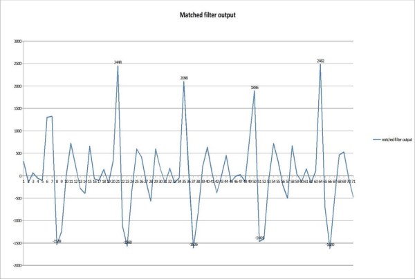
In the graphic that is labeled with matched filter output, you can see the output of the filter. the peaks are the matches with the filter. the negative peaks are also in agreement. if the robot were now outside, the peaks would be negative and the others positive. With the help of which peak comes first, you can now easily determine whether you are inside or outside.
You can also create and simulate your own signals with this link.
http://www.grauonline.de/alexwww/ardumower/filter/…
But how does the filter exactly work? Please check the sketch description for the receiver.
If you would like to know this down to the smallest detail and would like more information about the perimeter wire, visit the ardumower.de homepage
Step 2: Build the Transmitter Wire
Now we need some driving electronics which is sending the “unique” signal throught the wire. The easiest way to do this is an Arduino Nano and a L298 Motor driver module. You can’t simply shift on and off with a transistor. You won’t get an alternating current you need because in the off times no current will induced in the receiver coil. The perimeter wire needs about 1A to 2A it depends it depends on the area to be covered. The power resistor depends which current you want at 12V. The best thing to do is to first check the resistance of the wire. Then you can calculate the resistance of the power resistor. You will need 12 Ohms for 1 amp at 12 Volts. So if your wire have 2 Ohms you will need a 10 Ohms power resistor.
Upload the following sketch to the Arduino Nano:
matched_filter_sender_final.ino
What is happening in this sketch.
Timer1 from the Aruduino is configured to generate an interrupt at 10Khz frequency.
In this timer ISR the signal is shifted out over pin D2 and D3.
You can change your signal if you edit the arrey “H” and the variable “signal_length” please check it first at the matched filter simulator.
Step 3: Build the Receiver Circuit
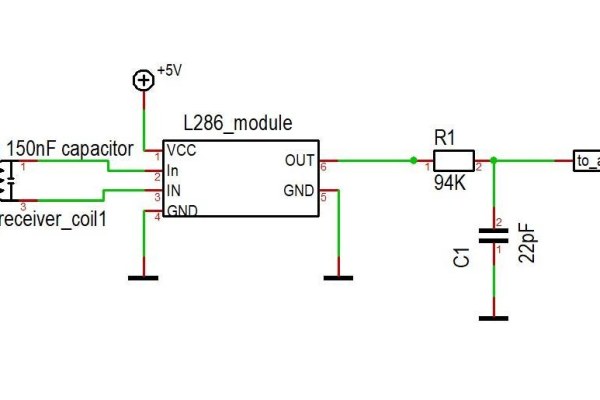
First you will need a receiver coil. I have tested dozens of coils. The coil of a Finder 24V DC relais without iron core works best.
Next you have to solder a 150nF foil capacitor in parallel with the coil. The capacitor smooths the signal and filters out high frequency interferences. Now you can connect the coil with the L286 amplifier module to the input side. The 100microFarad capacitor on the module must be bridged otherwise your signal is not correct.
Now we have to build a RC filter. The module produces some noise which correlate with the signal and make it noisy. For the fIlter you will need a 94K resistor and a 22pF ceramic capacitor.
The output of the filter is finally connected with the Arduino at the A0 pin.
Step 4: Programm and Test the Cirucit
If you open the matched_filter_receiver.ino you will notice some tabs this is your “library” i am working on a library but this is at the moment the best way.
with #include “perimeter.h” can you include the perimeter tabs.
now you have to configure the hardware for receiving the signal.
in the void setup() function you have to write PerimeterConfigure();
follow is happening:
Timer1 is used and set to 10khz interrupts
analog to digital converter is set to second highest speed.
some global variables are generated.
Now you can in void loop() trigger a signal recording and filtering with “getPerimeter(analogPin)”.
the return value is the signal strength of your signal. If it returns a zero no valid signal is detected.
What is happening in there?
first of all 150 samples will be recorded from the analog pin.
Then it goes throught the first matched filter algorythm. It outputs a characteristic filter courve.
The second matched filter searches for exactly this courve.
Now it searches for peaks an will it store in a pointer variable.
After a mean error is generated the peak and the mean are compared. If certain prerequisites have been met the pionter variable will be returned.
You can use the serial plotter and the showData(); function (important: after the getPerimeter(); function) to show the filter output.
And now nothing should stand in the way of your lawnmower project
Source: Perimeter Wire Using Matched Filter
- How does a perimeter wire work?
A perimeter wire sends a magnetic signal that induces a current in a receiver coil; the signal phase mirrors outside the wire, allowing the robot to distinguish between inside and outside. - What makes the signal unique and resistant to interference?
The signal uses a 31-step pattern that switches alternately between high and low states with varying times, making it distinct from other 8kHz sources like electric scooters. - Can I use a simple transistor to drive the perimeter wire?
No, you cannot simply switch on and off with a transistor because you need an alternating current during off times to induce current in the receiver coil. - Which component works best as a receiver coil?
The coil of a Finder 24V DC relay without an iron core was tested and found to work best. - Why must the 100microFarad capacitor on the amplifier module be bridged?
Bridging this capacitor ensures the signal is correct; leaving it unbridged results in an incorrect signal. - How do you calculate the power resistor value?
You check the resistance of the wire first, then calculate the needed power resistor to achieve roughly 1 amp at 12 volts based on the total resistance. - What happens if the getPerimeter function returns zero?
If it returns zero, no valid signal has been detected by the system. - How can you visualize the filter output during testing?
You can use the serial plotter and the showData function after calling getPerimeter to display the filter output curve.