Summary of PECS Communication Board
This article details the construction of a custom, battery-powered Picture Exchange Communication System (PECS) board designed for individuals with limited communication abilities. The project uses laser-cut MDF for a durable enclosure and features 16 buttons that trigger recorded audio messages via an Arduino Pro Mini and DF Mini Player. It emphasizes affordability, flexibility in language, and ease of use for those with poor motor skills, including a low-battery warning system and USB charging capabilities.
Parts used in the PECS Communication Board:
- Arduino Pro Mini 3.3V 8Mhz
- DF Mini Player
- Micro SD Card
- TP 4056 Charging Module
- Speaker 8 Ohm 40mm diameter
- Battery 3.7V 1700mAh
- Micro USB Breakout Board
- Micro Switch
- 5mm LED
- 220R Resistor R3
- 12k Resistor R2
- 33k Resistor R1
- 3mm MDF boards
- Copper strips and foil
- Laminating foil or transparent film
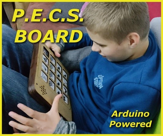
The Picture Exchange Communication System, or PECS, allows people with little or no communication abilities to communicate using pictures. People using PECS are taught to approach another person and give them a picture of a desired item in exchange for that item. By doing so, the person is able to initiate communication.
A child or adult with autism can use PECS to communicate a request, a thought, or anything that can reasonably be displayed or symbolized on a picture card.
I know you can buy such boards, but they are not cheap or flexible enough.
You could also use a tablet, but Scott has already smashed 2 smartphones and my tablet. This one is sturdy, cheap and has a lot of options. So you can also just make several.
The advantage is that the buttons are assigned to individual mp3’s, and you can then easily exchange them. You can also use any language for your PECS. If you don’t want to record the words yourself, you can also use text to speech and download them as mp3’s.
Step 1: Design and CAD Files
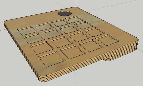
I have chosen this shape and size so that it fits well in the hand and the symbols are easy to see. The button size is also ideal for people with poor motor skills.
I drew a case in Sketchup to get a better idea of it.
Since the parts are laser-cut from 3mm MDF, I made a layered construction.
Then I drew all the parts in QCAD and lasered them out. To use them with my lasercutter, I had to convert the dxf file to a svg file. All the files are in this step, or they can be downloaded here.
Step 2: The Enclosure
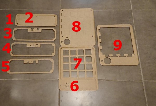
The enclosure is made of 3mm MDF boards that have been laser-cut. Of course, it should also work with a hobby saw.
The Parts 1,3,4 and 5 are glued together. Insert 3mm nuts into part 4. These are used to fix the lid 2 later with 3mm screws.
The result of 1,3,4, and 5 is then glued to 8. 6,8 and 9 are also glued and 3mm nuts are also inserted in 8. These hold the cover 7 in place, as this is removable for changing the cover sheets.
Step 3: Keyboard Matrix
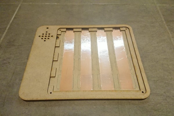
For the sixteen buttons, I built a DIY membrane keyboard. Self-adhesive vertical copper strips are glued to the underside.
The upper side consists of adhesive copper foil applied horizontally to a plastic sheet from a loose-leaf binder. Cardboard was used to separate the two foils. Then the wires could now be soldered to the copper strips, four to the back and four to the membrane.
Step 4: Cover Sheet
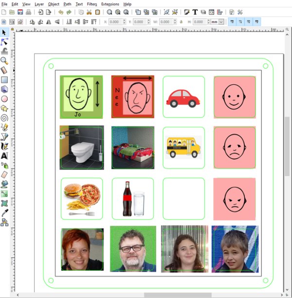
The cover sheet with the pictures is simply a printed picture for which a template has been created so that you can make them yourself without any problems. Afterwards, the sheet is simply sealed in laminating foil so that the pictures are protected against abrasion.
Alternatively, you can also stick a transparent film on the front.
Cut off along the black line.
Now insert the sheet and screw the cover on.
Step 5: Electronics
All the electronics are mounted on the back of the PECS board. The heart of the whole thing is an Arduino Pro Mini that runs at 8MHZ, so it only needs 3.3V. A DF mini player with micro SD card is responsible for the sound.
A TP4056 charging module charges and controls the battery.
A fully charged LI IO battery has a maximum voltage of 4.2 volts. The Arduino and the DF Mini Player still function at 3.2 volts, so everything is perfect for battery operation.
The DF mini player has 2 Watt output power, which is quite sufficient. Its TX and RX lines are connected to the Arduino. This allows the microcontroller to retrieve the files directly. I have written a small manual for the DF mini here. Its USB+ and – lines are soldered to the USB connector. This way the MP3’s can be written directly from the PC to the SD without having to remove it. At the same time, the battery is charged via the USB connector.The 8 wires of the matrix are also soldered to the Arduino. A voltage divider on the microcontroller monitors the battery status, and at 3.3V it issues a “Battery Low” warning.
The VCC of the Arduino Pro Mini is used to power the controller, so I bypass the 3.3V voltage regulator. Normally, the RAW input is used, which makes no sense with 3.7V battery operation, as I have to apply at least 4 volts here. A fully charged battery would still work, but not for very long.
The 5mm LED has been ground down so that it does not protrude at the front, and the light is now diffuse.
Part List:
- 1x Arduino Pro Mini 3.3V 8Mhz
- 1x DF Mini Player
- 1x Micro SD Card
- 1x TP 4056
- 1x Speaker 8Ohm 40mm diameter
- 1x Battery 3.7V 1700mAh (can be more or less Amps)
- 1x Micro USB Breakout Board
- 1x Micro Switch
- 1x 5mm Led
- 1x 220R Resistor R3
- 1x 12k Resistor R2
- 1x 33k Resistor R1
The Software can be found here https://github.com/awall9999/ScottCom
Step 6: Software
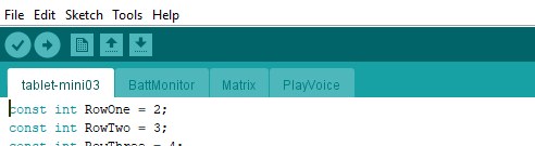
I have used several tabs in the Arduino IDE to keep the programming clearer.
Here are some explanations of the function
As you can see, the software consists of the main programme (Tablet-Mini03), the BattMonitor, the Matrix and the PlayVoice Tab.
The main programme defines all the variables that are used. Otherwise it checks whether a key has been pressed. A timer checks how long no key has been pressed in order to give an info via sound after 5 minutes that the board is still switched on (030.mp3).
The battery status is checked every 3 minutes. If the voltage drops below 3.3V, the battery low warning is played (020.mp3).
The BattMonitor works by using the analogReference(INTERNAL) in the main programme. This sets the measurement reference to 1.1 volts.
R1 (12K) and R2 (33K) function as voltage dividers. This can be calculated here: /https://www.peacesoftware.de/einigewerte/spannungsteiler.html
This way the Arduino can monitor the battery and set the variable BatteryLow to true at 3.3V.
The matrix, scans one row after the other and then per row the individual buttons. If a button was pressed during the scan, this is recorded in the ResultMatrix variable. The value is normally “0”. Otherwise, the variable contains the number of the button pressed.
The PlayVoice part, controls the DF MINI PLAYER via the serial interface. I do not use the ready-made LIB, but I have written my own control software.
This TAB consists of 3 VOIDs.
void ResetVoice, Sends a reset sequence to the DF Mini. (to stop a sound file) void VolumeVoice, sets the volume.
void PlayVoice, plays the sound file that was previously set.
DFDataFile[] = {0x7E,0xFF,0x06,0x0F,0x00,0x01,0x00,0xEF} is the data that is transmitted to the DF MINI, where the sixth data string defines the sound file (Bold). Then this data set is simply sent to the DF MINI via the For loop.
The Software can be found here https://github.com/awall9999/ScottCom
Step 7: The File Structure of the SD Card in the DF Mini Player
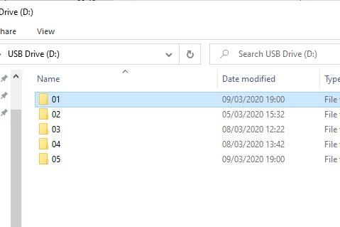
Connect the Pecs board with an micro USB Cable to a PC
The file folder 01 is accessed in the root directory, but you can create several, and then switch between the templates by renaming them.
The MP3 files are then uploaded inside the file folder, where 001.mp3 stands for the first button and 016.mp3 for the last.
020.mp3 should contain a text that indicates low battery power (e.g. Battery Low).030.mp3 should contain the text, indicating that the device has not been used for some time but is still switched on (e.g. Hello, have you forgotten me).
Free Text-To-Speech and Text-to-MP3
Step 8: The PECS Board
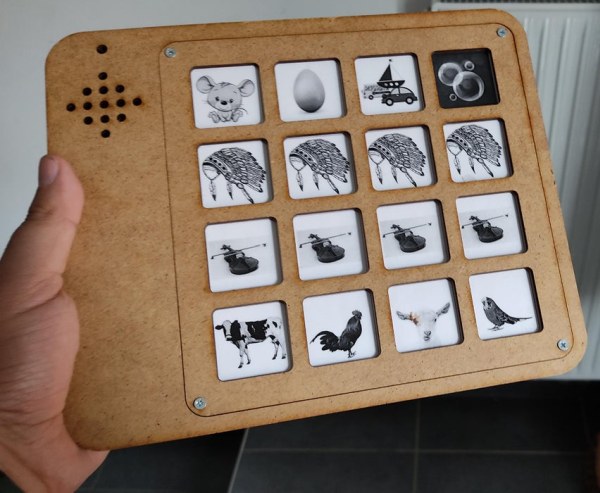
This is the prototype. I have already made some changes to the housing (cad file is updated). Now the screws fit, and one has been added to the lid.
For the placement of the components, I have now also provided cutouts, so that everything can be better held in place.
Externally, however, nothing has changed.
At the moment, I have music and sound files on the board so that Scott can learn how to use them. That seems to be working already.
The next step will be, to put pictures of food and drinks on the PECS board so that Scott can express his wishes at the dinner table. I will also try to practice colours, animals or other everyday things with him so that he has a way to communicate with us.
Step 9: Things to Do
- Adding the possibility to adjust the volume. (Done)
- Stopping the sound file by pressing the same button again (This can be advantageous for longer files).(Done)
- Remove the voltage regulator and the onboard power LED, from the Arduino, to send the board into standby. By removing these components, the power consumption will be reduced in sleep mode.
- Adding the possibility to switch between the sound folders.
The updates will then be available on my GITHUB.
It is best to always check Github, where I always post the latest changes.
https://github.com/awall9999/ScottCom
I hope you enjoyed this tutorial and could help someone with it.
Step 10: Software Update
Hello,I have just released the new software for the PECS board on GITHUB. https://github.com/awall9999/ScottCom
Pecs board_V1.3
- Stop a music file by pressing the same button again.
- Adjust the volume in four steps. Simply press button 1,2,3 or 4 for 2 seconds, until the music file is played as confirmation. 1 stands for soft and 4 for loud.
- The volume setting is stored in the internal EEPROM.
Enjoy the new features.
Source: PECS Communication Board
- How does the device initiate communication?
The user presses a button which triggers an MP3 file played by the DF Mini Player to request items or express thoughts. - Can I use different languages for the sound files?
Yes, you can record your own words or download text-to-speech files as MP3s in any language. - What happens if the battery voltage drops below 3.3V?
The system plays a specific warning sound file, such as Battery Low, to alert the user. - How are the MP3 files organized on the SD card?
Files must be placed in folder 01, where 001.mp3 corresponds to the first button and 016.mp3 to the last. - How do I update the software without removing the SD card?
You can connect the board to a PC via the Micro USB connector to write MP3s directly to the SD card. - What is the best way to protect the picture cover sheet?
Seal the printed pictures in laminating foil or stick a transparent film over the front. - How do I adjust the volume on the updated version?
Press button 1, 2, 3, or 4 for 2 seconds until a confirmation sound indicates the desired volume level. - Does the board have a feature to stop a playing sound?
Yes, pressing the same button again will stop the currently playing music or voice file.