Summary of PCB – Skateboard Floodlight V2
This article details the construction of compact, custom LED skateboard truck risers using 3D printed parts and custom PCBs. Unlike a previous version limited to hand tools, this project employs advanced fabrication techniques including SMD soldering and OSH Park PCB ordering. The system features wireless control via an Arduino-based remote and nRF24L01 radios, utilizing salvaged lantern LEDs and lithium-polymer batteries housed in ABS-printed enclosures.
Parts used in the LED Skateboard Truck Riser V2:
- Autodesk EAGLE PCB design software
- SMD Heat gun
- Soldering iron
- Solder wick
- Heat gun or mini-torch for heat shrink tubing
- Scissors
- Precision tweezers
- Hobby knife
- Hot glue gun & glue sticks
- Super-glue
- Drill & assorted drill-bits
- Wire cutter/stripper
- SparkFun AVR pocket programmer
- 3D printer or 3D printing service
- Assorted heat-shrink tubing (3/32", 1/8", 3/16", ¼")
- Arctic Silver Thermal Epoxy
- Fine gauge solid core wire (26AWG or 28AWG)
- Adafruit Micro Lipo charger
- 2x LED lanterns
- Skateboard bruh
- nRF24 radio modules
- ATMega328 boards
- Battery-manager boards
- MOSFETs
- Arduino UNO
- ATtiny85 microcontrollers
- Ice-Block PCBs
A while back, we constructed a pair of LED skateboard truck-risers. That project was intentionally created without the aid of advanced tools and techniques.
We decided to try the concept again but without limiting ourselves. This time around we used custom designed PCBs and 3D printed parts. There was no limiting ourselves to hand tools and whatever we could purchase from off-the-shelf sources.
The results were new truck risers that are just about the size of the truck base itself. Compared to the first version these are a only a small fraction of the original size. More what we originally wanted to do.
Step 1: Gather the Tools
– Autodesk EAGLE PCB design software
– SMD Heat gun
– Soldering iron
– Solder wick
– heat gun or mini-torch for heat shrink tubing
– scissors
– precision tweezers
– hobby knife
– hot glue gun & glue sticks
– super-glue
– a drill & assorted drill-bits
– wire cutter/stripper
– SparkFun AVR pocket programmer or something equivalent
– 3D printer or 3D printing service
Step 2: Procure the Parts and Materials
Note that the quantities listed are for EACH LED truck-riser and one remote-control.
External PCB parts
– Assorted heat-shrink tubing (3/32”, 1/8”, 3/16”, ¼”)
– Fine gauge solid core wire, 26AWG or 28AWG will do
– A lithium-polymer management board like the Adafruit Micro Lipo charger
– 2x LED lanterns
– A skateboard bruh
Step 3: Functional Block Diagram
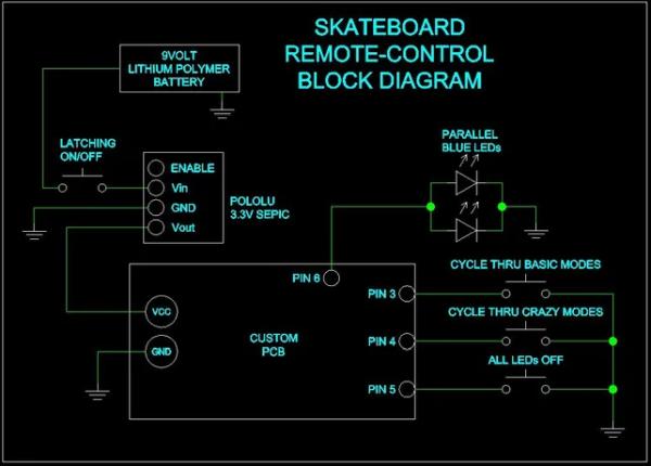
This is how the overall system functions for both the truck riser and the controller.
Step 4: Order the PCBs From a Board-house
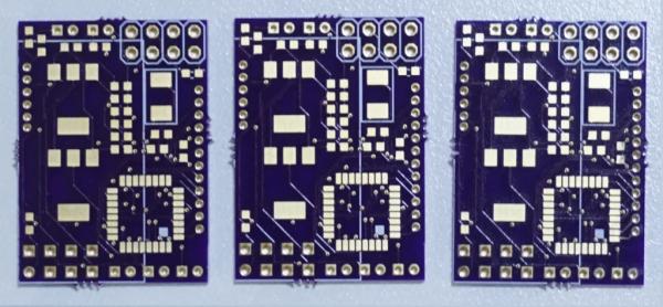
You could go anywhere to get your boards made, but we prefer OSH PARK. Their prices are hard to beat and the lead times, while not the absolute fastest, are very reasonable. All you have to do is ZIP up the Gerber files, and upload them to the OSH PARK upload page.
The picture shows the blank PCBs ready to go. Only three are needed for this project, but we got extras made. Just in case.
Also attached to this post are the gerber files necessary for ordering from OSH PARK.
Step 5: Populate the PCBs With Components
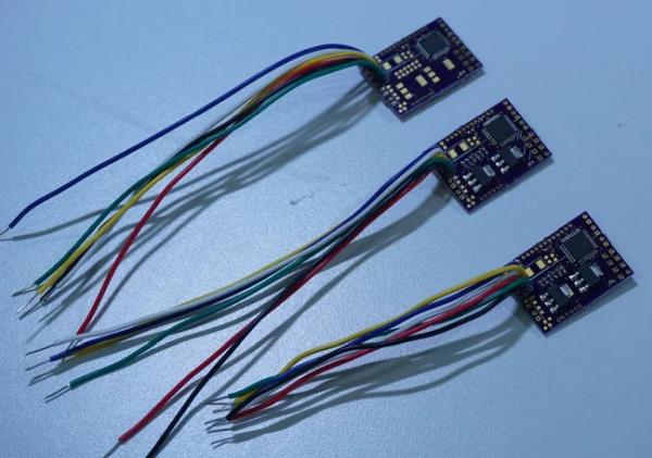
With the iron and SMD heat gun, solder components to the boards. Use solder wick to pick up any excess solder around the SMD components. If it looks like you removed all the solder with the wick, don’t worry, you didn’t. There is almost always enough solder left to do the job. Solder the nRF24s to the PCBs last so that it doesn’t get in the way of installing the other components.
Solder up three pairs of ATMega328 boards and battery-manager boards. Two pairs will be used for the trucks, and the third pair will go into the remote control.
The board for the remote control is the same as the truck-riser boards except for the MOSFETs, and their supporting components are left off.
(Picture 1) Two truck-riser boards and at the top, a board for the remote-control. Notice that the remote board doesn’t have the MOSFETs installed. The nRF24 radios have not been installed yet.
(Picture 2) The truck-riser boards with their nRF24 radio modules installed.
Step 6: Program the Boards Part 1
Because the remote-control is controlled by an Arduino, it is very straightforward to program.
If the boards already have their nRF24 radios soldered on, then you must use the 3.3-volt regulator to supply power to the board. A lot of programmers, including the SparkFun AVR pocket programmer used here, supply 5-volts via their programming header. The nRF24L01 cannot tolerate anything over 3.3-volts. Without burning
If the radio isn’t installed on the board, then program away.
Step 7: Program the Boards Part 2
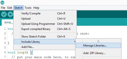
Open the “library” manager by going to Sketch -> Include Library -> Manage Library.
Step 8: Program the Boards Part 3
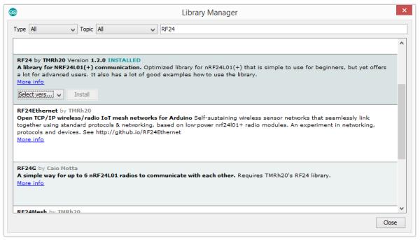
Do a search for “RF24” to bring up and the RF24 by TMRh20 library. Select the latest version of the library and install it.
Open the Arduino IDE and load the remote-control sketch. Set up the IDE for uploading to an UNO and hit the upload button.
A quick indication of whether the upload and circuit are working properly, is that the LED on the breadboard will briefly flutter each time the button is pressed.
The Arduino IDE does not come with the cores for programming the ATtiny85. A core is a file that tells the Arduino IDE
how to handle a microcontroller or an Arduino board. Follow the LINK to the GitHub page with ATtiny cores. Instructions for installation will be found on the GitHub page.
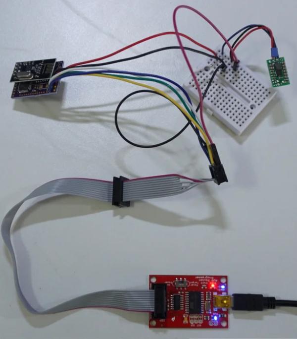
This schematic shows the connections between an UNO and an ATTiny85 for In-System-Programming. Use jumper wires to connect an UNO to the ISP header on an Ice-Block PCB.
Shown here is where the PCB header pins go to on the UNO.
Step 9: Program the Boards Part 4
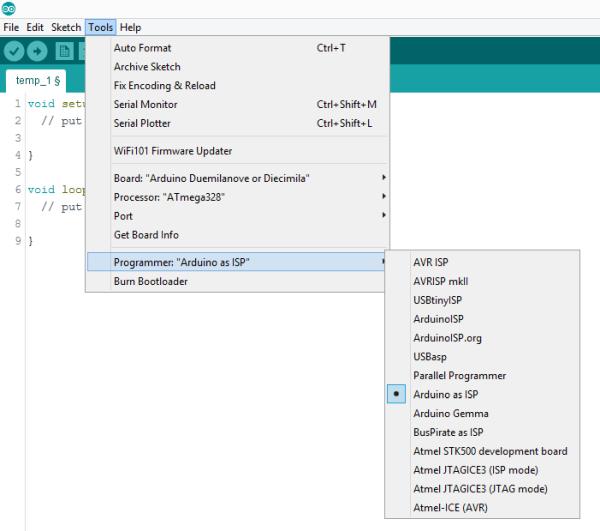
Load the “Ice Block PCB_Rx_1.ino” sketch. The ice-block PCBs are programmed with an Arduino UNO setup to function as an ISP (in-system programmer). Set the programmer type to “Arduino as ISP” in the dropdown menu.
Step 10: Program the Boards Part 5
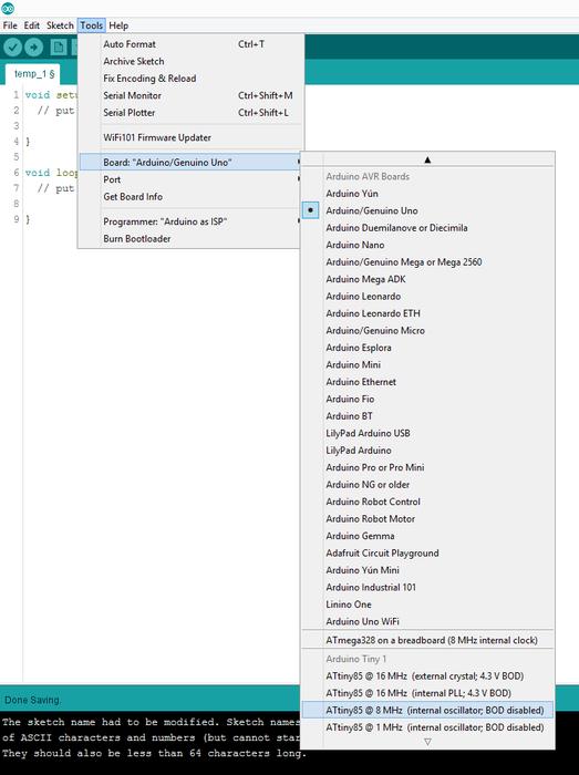
Select the ATtiny85 with an 8MHz internal oscillator. This option wouldn’t be available if you didn’t install the ATtiny 85 cores. Finally, upload the sketch.
Step 11: Build a Remote-Control
The remote-control is built on the skateboard-truck PCB. The MOSFETs and their support components are not installed. However, if your version of the remote-control has need of some MOSFETs, then go ahead and solder them to the board.
The remote-control circuit is built around an Arduino UNO. Build the remote-control circuit onto a breadboard. You will have to use an adapter for the nRF24L01 module because its pin spacing is not compatible with the 0.100” hole spacing of breadboards.
Fasten the remote-control into a cardboard box with a few globs of hot glue. The nRF24 seen here is electrically identical to the types used for the ice-block PCBs except that it has an external antenna on it for extra range. Notice the on-off button jammed into a hole in the cover of the box.
Step 12: Disassemble the Lanterns for Their LEDs Part 1
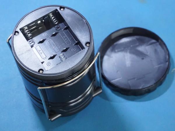
This isn’t very technical, but it’s tricky.
Remove the battery cover on the bottom of the lantern. Use a screwdriver to remove the screws holding the battery tray into place.
Step 13: Disassemble the Lanterns for Their LEDs Part 2
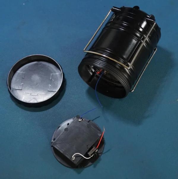
Pull the battery tray out and clip the wires running to it.
Step 14: Disassemble the Lanterns for Their LEDs Part 3
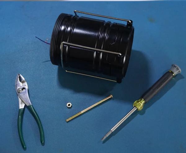
Use a screwdriver and a pair of pliers to remove the long screw running down the center of the lantern.
Step 15: Disassemble the Lanterns for Their LEDs Part 4
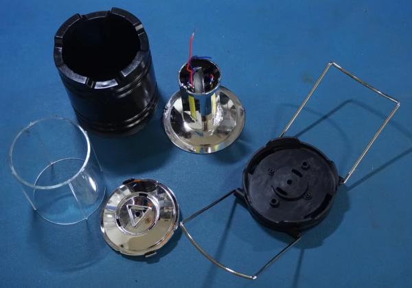
Pull the pieces of the lantern apart.
Step 16: Disassemble the Lanterns for Their LEDs Part 5
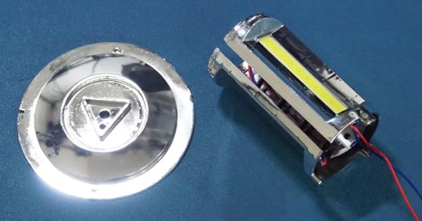
Pull the LED reflector array away from the base. It will pop off when you apply pressure.
Step 17: Disassemble the Lanterns for Their LEDs Part 6
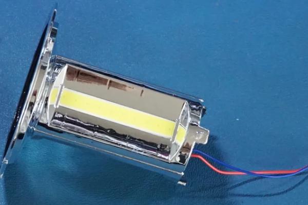
Unfold the LED reflector array. Gently pull the LED panels away from the reflector. You won’t have to pull very hard, the LEDs are held into place with a coup drops of melted plastic.
Step 18: Disassemble the Lanterns for Their LEDs Part 7
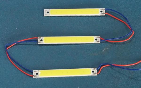
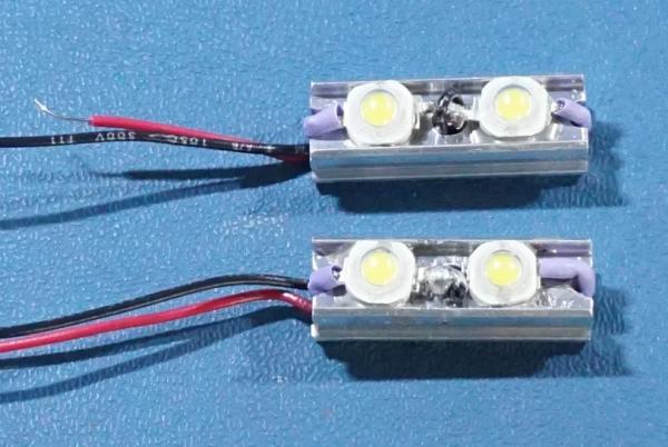
The LED panels. You will have to disassemble two lanterns to get enough LEDs for two truck risers.
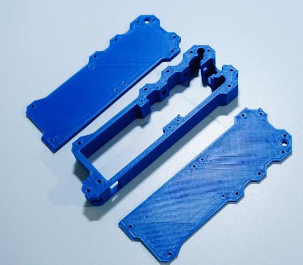
Step 19: Assemble the Truck-risers
Step 20: Testing Modes
Turn on the trucks and the remote. Wait until the LED stops flashing on the remote, then proceed.
Step 21: Final Thoughts
You are probably wondering, I was riding on 3D printed truck risers, did thy crack or break in any way? Not at all. These were printed in ABS with a full fill. I could even do tricks… however, I didn’t do too many, since I wasn’t sure how the ectronics would hold up.
What held us back from making this even small was the size of the LEDs and battery.
Perhaps in the future we could find smaller, more powerful LEDs.
But, battery tech doesn’t move as fast. So, we might be stuck with a similar power-pack.
Is version 3 on the way? Yes… we just need a little funding first. 🙂
Source: PCB – Skateboard Floodlight V2
- How can I power the board if the nRF24 radio is already installed?
You must use the 3.3-volt regulator because many programmers supply 5 volts which will burn the nRF24L01. - What library is required to program the nRF24 radio module?
The RF24 library by TMRh20 must be installed via the Arduino IDE library manager. - Does the remote-control circuit differ from the truck-riser circuit?
Yes, the remote board does not have MOSFETs or their supporting components installed. - Can I use standard breadboards for the nRF24L01 module without modification?
No, you must use an adapter because the pin spacing is not compatible with standard 0.100 inch breadboard holes. - What material was used to print the truck risers to ensure durability?
The risers were printed in ABS with a full fill to prevent cracking during tricks. - How do I identify if the upload and circuit are working properly?
An LED on the breadboard will briefly flutter each time the button is pressed. - Why did the authors need to disassemble two lanterns?
You need to disassemble two lanterns to gather enough LEDs for two truck risers. - What limits the size reduction of future versions of these risers?
The physical size of the LEDs and the battery technology currently limit further miniaturization.