Summary of FREE ELEKTOR CIRCUIT – ACOUSTIC IR REMOTE CONTROL TESTER
This circuit converts IR remote signals into audible sounds using a Vishay TSOP4836 receiver, a divide-by-2 IC, and a push-pull transistor stage to drive a loudspeaker. Powered by 3V from two AA batteries, it consumes minimal current. The design effectively translates high-frequency IR pulses into audio frequencies suitable for testing remote controls via sound output.
Parts used in the Acoustic IR Remote Control Tester:
- IR Receiver (IC1, specifically TSOP4836)
- Divide-by-2 IC (IC2)
- Transistors T1 and T2
- Loudspeaker
- Resistor R1
- Capacitor C1
- Two AA-batteries
In this circuit we use the output signal from a standard IR receiver (IC1 in the schematic of Figure 1) to drive a miniature loudspeaker. The IR receiver from Vishay used here is available for various frequencies ranging from 30 to 56 kHz. A large number of IR remote controls operate according to the so-called RC5 protocol that uses a frequency of 36 kHz. In our prototype we used a TSOP4836; and as the part number suggests, it is intended for 36 kHz operation. However, it will also ‘work’ at other frequencies, if they are not too different.
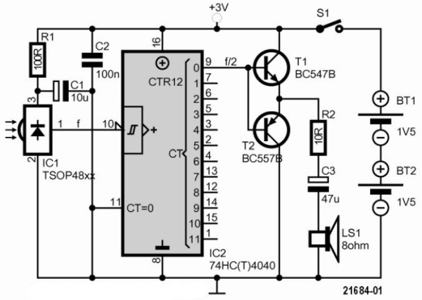
The signal at the output of the IR receiver is at too high a frequency to generate an appropriate sound signal; that is why we first pass the signal through a divide-by-2 IC (IC2). You can use the signal from any of the outputs, depending on your personal preference (we used output ‘0’ (pin 9) – the input signal divided by two).
We use this signal to drive a very simple push-pull output stage (T1/T2), that nevertheless has enough power to drive a small loudspeaker.
The circuit is powered from 3 V (two AA-batteries); the current consumption amounts to about 13 mA maximum (0.66 mA when idle). R1 and C1 decouple the power supply voltage for the IR receiver to prevent any potential interference from the output stage.
Read more: FREE ELEKTOR CIRCUIT – ACOUSTIC IR REMOTE CONTROL TESTER
- What frequency does the RC5 protocol use?
The RC5 protocol uses a frequency of 36 kHz. - Can the TSOP4836 operate at frequencies other than 36 kHz?
Yes, it will work at other frequencies if they are not too different. - Why is a divide-by-2 IC used in this circuit?
The signal from the IR receiver is too high in frequency to generate an appropriate sound signal directly. - Which output pin was used on the divide-by-2 IC?
Output '0' on pin 9 was used, which provides the input signal divided by two. - How much power does the circuit consume when idle?
The current consumption is about 0.66 mA when idle. - What is the purpose of R1 and C1 in the schematic?
R1 and C1 decouple the power supply voltage for the IR receiver to prevent interference from the output stage. - What type of output stage drives the loudspeaker?
A simple push-pull output stage consisting of transistors T1 and T2 drives the loudspeaker. - Does the circuit require more than 3 volts to operate?
No, the circuit is powered from 3 V using two AA-batteries.