Summary of PCB Designing in Proteus ARES
This tutorial concludes a Proteus series by demonstrating PCB design using Proteus ARES. The process begins with creating a circuit in Proteus ISIS, then generating a netlist to transfer the design to ARES. Users define the board boundary, place components, and utilize software intelligence for automatic route suggestions. Finally, the article details two routing methods: auto-routing via the Tools menu or manual routing by connecting component edges directly.
Parts used in the PIC Basic Circuit Project:
- Proteus ISIS
- Proteus ARES
- PIC basic circuit
- Board Edge block option
- Component option toolbar
- Auto Router tool
- Manual routing option
Hello friends, today’s the last post of this Proteus tutorial. I have tried my best to explain everything but knowledge is limitless so explore this software, play with it and you will know many new things. Today’s topic is about the PCB designing in Proteus. When you install Proteus, you have seen that along with ISIS there’s also another package named as Proteus ARES. This Proteus ARES is used for PCB designing. You should also check the Arduino UNO PCB Design for Proteus ARES.
In order to design the PCB in Proteus ARES, first you need to make the circuit of that PCB in Proteus ISIS. You can also make PCB directly but I recommend that use Proteus ISIS first, its quite the easy approach as you don’t need to do anything in it and the software intelligence helps you throughout the designing. Here’s the list of Top 10 PCB Design Software. So let’s get started with PCB Designing in Proteus ARES:
PCB Designing in Proteus ARES
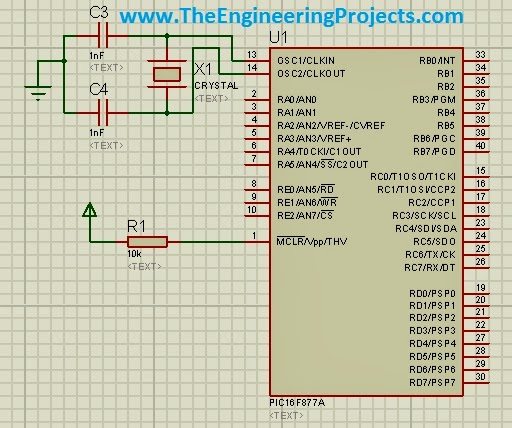
- As in this tutorial, I just want to give you an idea of How to design PCB that’s why I haven’t taken difficult circuit, just a simple PIC basic circuit.
- First design your circuit in Proteus ISIS as shown in below figure:
- After you got sure that your circuit is perfect and ready for designing, then click on the Tools and then Netlist to ARES as shown below:
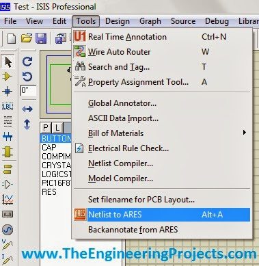
- After clicking, Proteus ARES will be opened.
- Now in Proteus ARES, select the block option from left toolbar and also make sure that you selected Board Edge in the below drop down menu as shown in below figure:
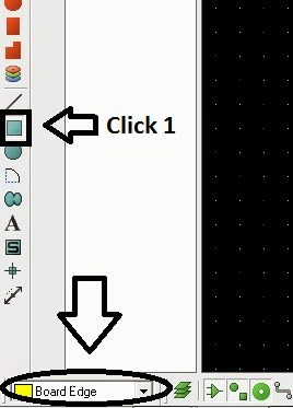
- Now make a rectangular block in the workspace, this block is actually the boundary of your PCB.
- You can set its proper dimensions and can also re-size it manually using the mouse.

- Now select the component option from the left toolbar, it will show all the components used in your circuit.
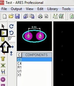
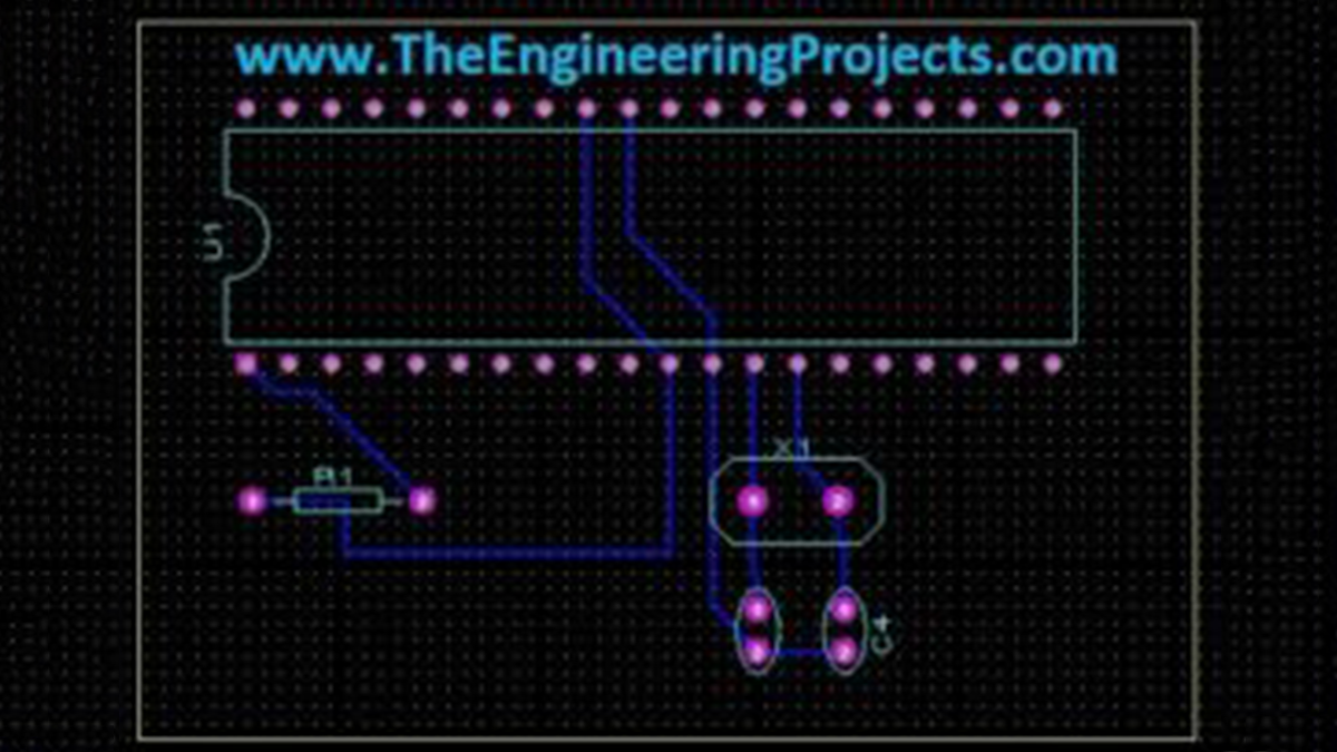
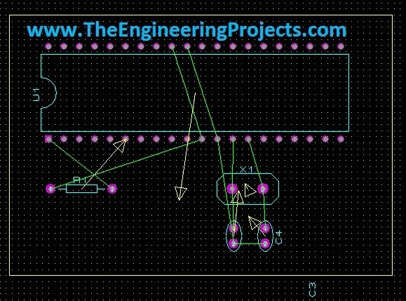
- Place all these components in the workspace one by one as shown below. These green lines shown in the below image is actually the software intelligence.
- Using the circuit, it gives us the routes automatically and we don’t need to panic any more just need to follow these route, if we are doing manually routing.
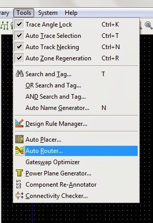
- Now there are two ways of adding routing, first method is auto routing.
- To do auto routing, click on Tools and then Auto Router and a property box will open where you can set many different option for routing like the width of route and the PCB layers etc.
- After selecting your properties just click on Begin Routing.
- And then a magic will start and you PCB will become ready as shown in below figure:

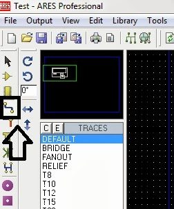
- Second method is manual routing, you can do manual routing by clicking the edges just like we connect wires in Proteus ISIS. For manual routing select the option shown in below figure and start routing.
- That’s it. I don’t think its much difficult. I am gonna stop this tutorial here. I have tried my best to share my knowledge about Proteus. IF you guys having any problem in part of this tutorial, feel free to contact me. Take care.
-
What is Proteus ARES used for?
Proteus ARES is used for PCB designing. -
How do you start designing a PCB in Proteus ARES?
You must first make the circuit in Proteus ISIS and then click on Tools followed by Netlist to ARES. -
Which option should be selected to create the PCB boundary?
You should select the Board Edge drop down menu and use the block option from the left toolbar to make a rectangular block. -
What helps users follow routes automatically during design?
The software intelligence displays green lines that show routes automatically based on the circuit. -
How can you perform auto routing in Proteus ARES?
Click on Tools and then Auto Router to open a property box where you set options like width and layers before clicking Begin Routing. -
Is it possible to route manually instead of using auto routing?
Yes, you can do manual routing by selecting the specific option and clicking edges just like connecting wires in Proteus ISIS.