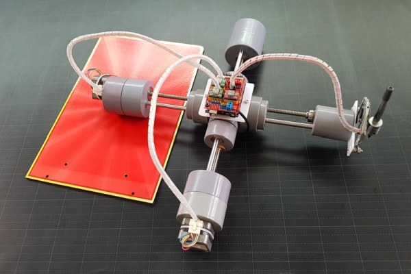
This is my P-CNC plotter which is laid out and disguised as a quadruped robot. Today, I’d like to share how I made it. It was quite simple, no 3D printer required, just need my meticulousness, care and a little patience.
Please check the brief description and how P-Plotter works in the video below before getting started.
Step 1: Supplies
Main components are as follows:
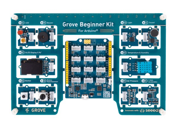
If you are new to Arduino, you can buy a kit named “Grove Beginner Kit for Arduino” with 10 additional Grove Arduino sensors all in one piece of the board. All modules are pre-wired, no breadboard and jumper cables required. And it will bring you the simplest way to get started with Arduino.
- 1pcs x Arduino CNC Shield V3 GRBL: Amazon – Banggood.
- 3pcs x Stepper Motor Driver A4988: Amazon – Banggood.
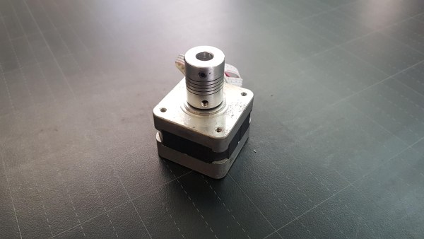
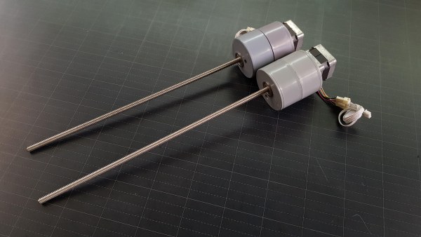
- 2pcs x Stepper motor NEMA 17: Amazon – Banggood.
- 1pcs x Old CD/DVD Burner Writer Rom Player Drive – Compact Type: Amazon – Banggood.
- 2pcs x Round Bar Shaft Rod Diameter 8mm, Length 400mm: Amazon – Banggood.
- 2pcs x T8 Lead Screw 2mm Pitch, 8mm Lead , Length 400mm with Copper Nut: Amazon – Banggood.
- 12pcs x Ball Flanged Shielded Bearings 8 x 22 x 7mm: Amazon – Banggood.
- 1pcs x Aluminum Flexible Shaft Coupling, Inner Hole Size: 10mm x 10mm: Amazon – Banggood. It is used to clamp the pen/ pencil.
- 2pcs x Aluminum Flexible Shaft Coupling, Inner Hole Size: 5mm x 8mm: Amazon – Banggood.
- 2pcs x XH2.54mm – 4P 20cm Wire Cable Double Connector: Amazon – Banggood.
- 1pcs x 5mm DC Female Power Plug: Amazon – Banggood.
- 1pcs x Power Supply 12VDC: Amazon – Banggood.
- 1pcs x Clear/White Acrylic, size A3, thickness 5~10mm: Amazon – Banggood.
- 1 meter x 8P/16P Rainbow Ribbon Cable: Amazon – Banggood.
- Some small cable ties, cable spiral wrap, bolts and nuts.
PVC pipes and its fittings:
- 1 meter x PVC Pipe Ø42mm.
- 1 meter x PVC Pipe Ø60mm.
- 1pcs x Cross PVC Pipe Ø42mm.
- 6pcs x End Cap PVC Pipe Ø42mm.
- 6pcs x End Cap PVC Pipe Ø60mm.
Tools:
- Drilling machine with drill bit 8mm and drill bit hole 22mm.
- Hand saw.
- Soldering machine.
- Big scissor.
Softwares:
- GRBL firmware.
- Inkscape with Gcodetools extension.
- Universal Gcode Sender.
Step 2: Schematic
The schematic & connection diagram is very simple.
- Plugging the CNC shield on the Arduino Uno R3.
- Plugging three stepper motor drivers A4988 on the CNC shield at X, Y and Z label position.
- Connecting the cables from stepper motor drivers to three stepper motors.
That’s all!
The NEXTPCB support me for this project. If you have a PCB project, please visit the NEXTPCB website to get exciting discounts and coupons.
- Only $0 for 1-4 layer PCB Prototype: https://www.nextpcb.com/pcb-quote?act=2&code=tunen…
- New customer get $100 coupons, register at: https://www.nextpcb.com/register?code=tunendd
Here are mid-summer sales at NextPCB:
- Up to 30% off for the PCB orders.
- Up to 20% off for the PCBA orders.
Step 3: Drilling and Cutting Works
Due to the COVID-19 pandemic, my city was locked down, I couldn’t go out to buy materials and electronic equipments. So I had to use what remained in my hand, especially PVC pipes and its fittings.
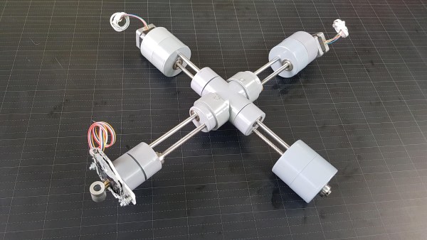
Firstly, I imagined a robot-shaped CNC plotter and sketched it out on paper to estimate the pipe fittings. And I named it “P-Plotter” because it was made of PVC pipe. My P-Plotter shape looked like the picture below and my goal is to drill total 12pcs of PVC end cap Ø42 and Ø60mm to thread the leadscrews and shafts through these holes.
Drilling is the most important work of this project, deciding the success or failure. We should buy a few extra end caps in case of incorrect drilling. Because this inaccuracy is easy to happen when we drill by hand.
a. Drilling PVC end caps Ø42mm.
Firstly, I drilled a big 22mm diameter hole. I have marked its center by placing a bearing inside the end cap so that it was in contact with the wall of end cap. The small 8mm diameter hole’s center was drilled with a distance of 23mm from the big hole’s center. And two hole centers should align with the end caps center for a symmetrical mechanism.
Total 6pcs end caps Ø42mm were drilled with 2 holes.
b. Drilling PVC end caps Ø60mm.
- I did the same way with end caps Ø60mm with total of 4pcs.
- To mount the 2 stepper motors, I had to drill 4 more small holes on the end cap Ø60mm, around the big holes. Quantity needed: 2 pcs.
c. Cutting connecting pipes Ø42 & Ø60mm.
Connecting pipes should be cut in suitable length so that when we connected 2 end caps together, there is no gap between them.
- Connecting pipe Ø42 quantity needed: 5pcs.
- Connecting pipe Ø60 quantity needed: 3pcs.
After I connected 2 end caps together by a connecting pipe, it should be like this.
d. Cutting PVC cross Ø42mm
The PVC cross is a bit long so I had to cut it, about 28mm, to extend the XY axis working space.
Step 4: Inserting All Bearings and Copper Nuts Into the Drilling Holes
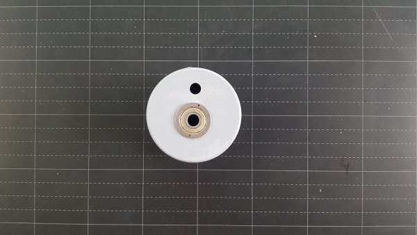
- Inserting bearing into 22mm diameter holes.
- Connecting 2 end caps and check whether it was aligned and symmetric together.
- Inserting bearings and copper nuts into end cap Ø42 and connecting 4 end caps to PVC cross. We should check with lead screws and shafts before fitting all end caps tightly into cross. Note that, two lead crews and shafts of the X and Y axes should be arranged horizontally and vertically relative to each other. By this way, they could get through the PVC cross without touching each other.
- The opposite side of cross.
Step 5: Y Axis Assembly Works
- Mounting flexible coupling 5mm x 8mm on the steppers motor shaft.
- Mounting stepper motor on the end cap and fixing lead screw into flexible coupling.
- Connecting with another end cap and inserting a shaft into 8mm diameter hole.
- Temporarily checking and aligning before fixing 2 end caps tightly at motor side.
- Building Y axis by threading a lead screw and shaft through the PVC cross.
- Locking the leadscrew end by one bearing and check the movement by hand.
Step 6: Control Board Pre-Assembly Works
I have mounted the control board in the center of P-Plotter. It is placed on the PVC cross as follows:
- I cut a small acrylic sheet, drilled 4 holes for mouting Arduino Uno and other 2 holes for mounting to PVC cross.
- I cut 2 small pipe support, 50mm diameter, about 25mm long. The pipe wall cutting side was used for clamping to PVC cross and the drilling holes side for mounting to Arduino Uno acrylic base above.
- Connecting pipe supports to Arduino Uno acrylic base, just for testing.
- These pipe supports should be clamped on the PVC cross before installing X axis, then later connected to the Arduino base by bolts.
Step 7: X Axis Assembly Works
- I built X axis as same as the Y axis at stepper motor side. I mounted stepper motor on the end cap and fixed leadscrew into flexible coupling.
- Clamping pipe supports on the PVC cross.
- Installing X axis by threading its lead screw and shaft through the PVC cross.
Step 8: Z Axis Assembly Works
Soldering cable to CD drive stepper motor and mounting one flexible coupling 10 x 10mm on the front side to clamp the pen.
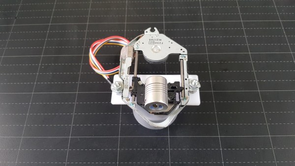
- On the back, I attached the CD stepper motor frame to a small acrylic sheet and mounted this acrylic sheet to end cap Ø42mm.
- Threading the lead screw and shaft through the end caps and locking the lead screw by bearing inside and outside of end cap.
- Z axis was done!
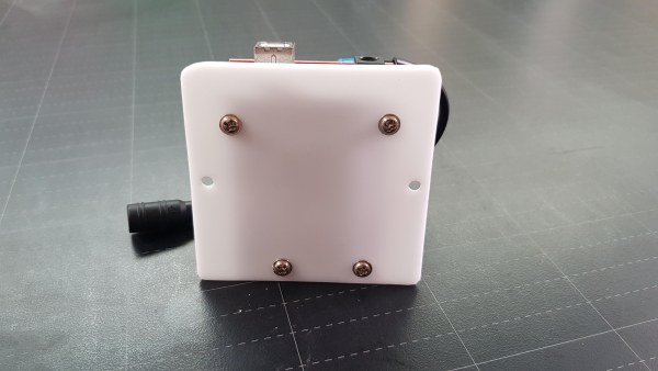
Step 9: Control Board Mounting Works
- Mounting control board base to pipe supports and tightening 2 bolts.
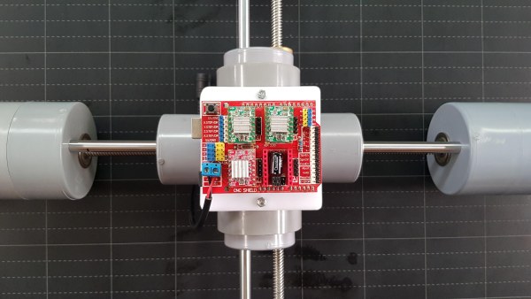
- Connecting all cables from stepper motors to CNC shield. These cables are fixed by cable ties and cable spiral wraps.
- With this design, when P-Plotter working, the X-axis would slide back and forth so I used a wall calendar cover which is very flat, smooth and hard enough, as a working surface. Or we can use an A4 size acrylic sheet.
Step 10: GRBL Firmware Uploading and Parameter Setting
1. Uploading GRBL firmware to Arduino Uno.
- Download GRBL firmware files.
- Copy GRBL folder to C:\Users\Administrator\Documents\Arduino\libraries\
- Open Arduino IDE, from File menu click Examples‣GRBL‣grblUpload.
- Select the correct Port and Board (Arduino Uno) ‣Compile and Upload the code to Arduino Uno.
2. GRBL parameters setting for my P-Plotter are as follows:
| $0 | 10.000 | Step pulse time |
| $1 | 25.000 | Step idle delay |
| $2 | 0.000 | Step pulse invert |
| $3 | 0.000 | Step direction invert |
| $4 | 0.000 | Invert step enable pin |
| $5 | 0.000 | Invert limit pins |
| $6 | 0.000 | Invert probe pin |
| $10 | 1.000 | Status report options |
| $11 | 0.010 | Junction deviation |
| $12 | 0.002 | Arc tolerance |
| $13 | 0.000 | Report in inches |
| $20 | 0.000 | Soft limits enable |
| $21 | 0.000 | Hard limits enable |
| $22 | 0.000 | Homing cycle enable |
| $23 | 0.000 | Homing direction invert |
| $24 | 25.000 | Homing locate feed rate |
| $25 | 500.000 | Homing search seek rate |
| $26 | 250.000 | Homing switch de-bounce delay |
| $27 | 1.000 | Homing switch pull-off distance |
| $30 | 1000.000 | Maximum spindle speed |
| $31 | 0.000 | Minimum spindle speed |
| $32 | 0.000 | Laser-mode enable |
| $100 | 200.000 | X-axis travel resolution |
| $101 | 200.000 | Y-axis travel resolution |
| $102 | 53.333 | Z-axis travel resolution |
| $110 | 500.000 | X-axis maximum rate |
| $111 | 500.000 | Y-axis maximum rate |
| $112 | 500.000 | Z-axis maximum rate |
| $120 | 5.000 | X-axis acceleration |
| $121 | 5.000 | Y-axis acceleration |
| $122 | 5.000 | Z-axis acceleration |
| $130 | 150.000 | X-axis maximum travel |
| $131 | 150.000 | Y-axis maximum travel |
| $132 | 40.000 | Z-axis maximum travel |
The parameters which I have done the calibrations are highlighted in table above.
The acceleration parameters $120 and $121 should be set to a small value, to prevent shaking issues.
Source: P-CNC Plotter Disguised As a Quadruped Robot