I use Arduino Duemilanove With Motor Driver Shield
- Microcontroller ATmega168
- Operating Voltage 5V
- Input Voltage (recommended) 7-12V
- Input Voltage (limits) 6-20V
- Digital I/O Pins 14 (of which 6 provide PWM output)
- Analog Input Pins 6
- DC Current per I/O Pin 40 mA
- DC Current for 3.3V Pin 50 mA
- Flash Memory 16 KB (ATmega168) or 32 KB (ATmega328) of which 2 KB used by bootloader
- SRAM 1 KB (ATmega168) or 2 KB (ATmega328)
- EEPROM 512 bytes (ATmega168) or 1 KB (ATmega328)
- Clock Speed 16 MHz
Parts :
- 2 x DC Motor
- 5 x LED lamp ( I built it myself )
- 4 x 7segment
- 2 x DC Fan
- 1 x Automatic Spray
- Power supply 5volt Circuit
- Motor Driver L298
- Touch Switch IC555
- Limit Switch
- Accu 12V
- Transformator 2A
- Timing Belt
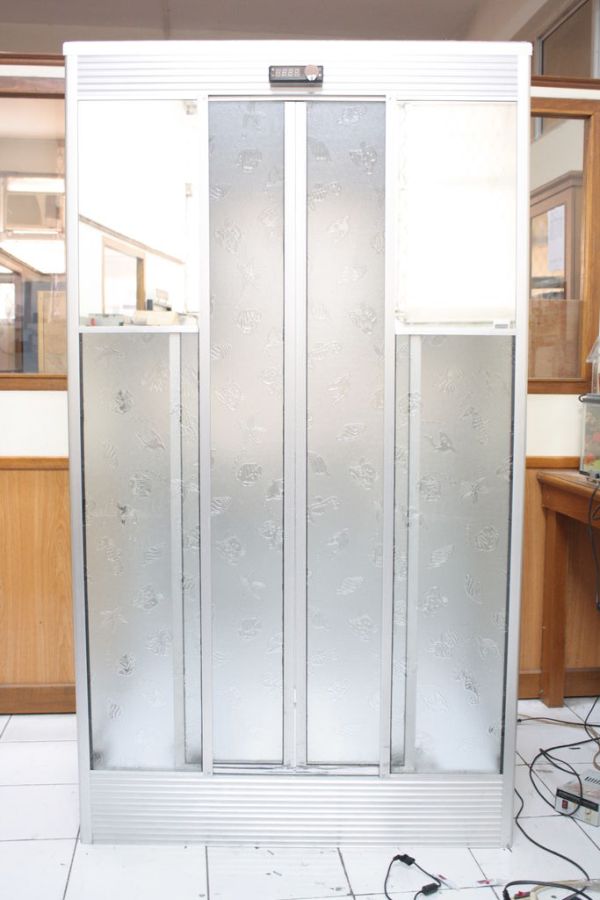
- Alumunium
- Mirror
- Glass
- Plywood
Step 1: The Controller
Arduino Motor Shield (L298N)
=================================================================================
Introduction
=================================================================================
This motor shield allows Arduino to drive two channel DC motors. It uses a L298N chip which deliveries output current up to 2A each channel. The speed control is achieved through conventional PWM which can be obtained from Arduino’s PWM output Pin 5 and 6. The enable/disable function of the motor control is signalled by Arduino Digital Pin 4 and 7.
The Motor shield can be powered directly from Arduino or from external power source. It is strongly encouraged to use external power supply to power the motor shield.
Logic Control Voltage5V (From Arduino)
Motor Driven Voltage4.8^35V (From Arduino or External Power Source)
Logic supply current Iss≤36mA
Motor Driven current Io≤2A
Maximum power consumption25WT=75
PWMPLL Speed control mode
Control signal level:
High2.3V≤Vin≤5V
Low-0.3V≤Vin≤1.5V
==================================================================================
Pin Allocation
==================================================================================
“PWM Mode”
Pin Function
Digital 4 Motor 2 Direction control
Digital 5 Motor 2 PWM control
Digital 6 Motor 1 PWM control
Digital 7 Motor 1 Direction control
“PLL Mode”
Pin Function
Digital 4 Motor 2 Enable control
Digital 5 Motor 2 Direction control
Digital 6 Motor 1 Direction control
Digital 7 Motor 1 Enable control
==================================================================================
Sample Code
==================================================================================
//PWM Speed Control
//Arduino PWM Speed Control
int E1 = 6;
int M1 = 7;
int E2 = 5;
int M2 = 4;
void setup()
{
pinMode(M1, OUTPUT);
pinMode(M2, OUTPUT);
}
void loop()
{
int value;
for(value = 0 ; value <= 255; value+=5)
{
digitalWrite(M1,HIGH);
digitalWrite(M2, HIGH);
analogWrite(E1, value); //PWM Speed Control
analogWrite(E2, value); //PWM Speed Control
delay(30);
}
}
=======================================
//PLL Speed Control
//Arduino PLL Speed Control
int E1 = 7;
int M1 = 6;
int E2 = 4;
int M2 = 5;
void setup()
{
pinMode(M1, OUTPUT);
pinMode(M2, OUTPUT);
}
void loop()
{
int value;
for(value = 0 ; value <= 255; value+=5)
{
digitalWrite(M1,HIGH);
digitalWrite(M2, HIGH);
analogWrite(E1, value); //PLL Speed Control
analogWrite(E2, value); //PLL Speed Control
delay(30);
}
}
==================================================================================
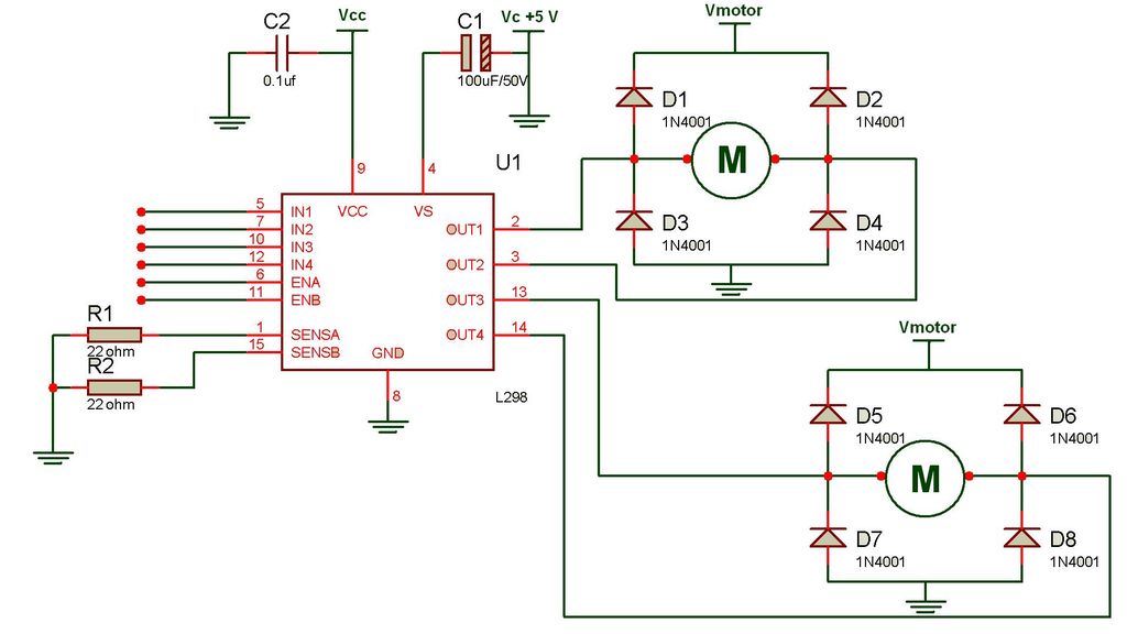
Motor Driver L298
=================================================================================
I use for Fan
The Code :
void kipas()
{
digitalWrite(kipasPin1, HIGH);
digitalWrite(kipasPin2, LOW);
digitalWrite(enablePin,HIGH);
delay(1000);
}
void kipas_mati()
{
digitalWrite(kipasPin1, LOW);
digitalWrite(kipasPin2, HIGH);
digitalWrite(enablePin,LOW);
delay(1000);
}
=======================================================================================
Source :
http://www.dfrobot.com/wiki/index.php?title=Arduino_Motor_Shield_%28L298N%29_%28SKU:DRI0009%29
PDF :
http://droboticsonline.com/ebaydownloads/L298_Motor_Shield_Manual.pdf
Step 2: Touch Sensor
====================================================================================
Touch Switch
====================================================================================
There are a number of different types of TOUCH PLATES and different effects
can be created by the circuit.
1. Touch a set of pads and the project turns on.
When the finger is removed, the circuit turns off.
The finger can touch the pads for any length of time.
We also include the feature where the circuit extends the ON period,
so the circuit stays on for a length of time after the finger is removed.
This is shown in Circuits A.
For more detail: One Touch Wardrobe using an Arduino