Summary of Oceania Midi Controller (for Make Noise 0-Coast and Other Synths)
The article describes building the "Oceania," a capacitive-touch MIDI controller designed as a tribute to Don Buchla and optimized for the Make Noise 0-Coast synthesizer. It explains the differences between East Coast (subtractive) and West Coast synthesis and how the 0-Coast combines elements of both. The project involves cutting copper-clad boards to create touch-sensitive "not-keys," wiring them to an Arduino Mega, and programming it to send MIDI signals to the synth. The controller offers a tactile and non-traditional keyboard interface inspired by Buchla's avoidance of piano-style keys.
Parts used in the Oceania MIDI Controller Project:
- Arduino Mega (mini recommended)
- 220Ω resistors
- Stereo 3.5mm phono socket
- Copper clad sheet (single sided, at least 9"x2 3/4")
- Stranded hookup wire (30AWG recommended)
- Solder
- Stereo TRS 3.5mm male-to-male cable
- Mounting material (e.g., stained solid oak, PVC sheet, 3D printed base)
In the past few years, a number of synthesizer manufacturers have been releasing “desktop semi-modular” instruments. They generally take the same form factor as the Eurorack modular synthesizer format and most are probably intended as a gateway drug into the world of modular. (As addictions go, it’s one of the safer ones.)
I fell for the marketing hard I’m afraid.
While I love the Moogs and Behringers, I kept reading about the Make Noise “0-Coast.” At the same time I was seeing these promotional videos featuring Suzanne Ciani, Kaitlyn Aurelia Smith, Todd Barton, Allesandro Cortini, etc. that beckoned me to (what was to me anyway) a new kind of music synthesis mindset: “West-coast synthesis,” it was called in general.
The general difference between this and what I grew up on (as it is usually explained) is that Bob Moog created “east coast” (or subtractive) synthesis with a focus on emulating traditional instruments by creating natural, basic waveforms and filtering out ends or bands of the spectrum while shaping the volume envelope. Don Buchla, on the other hand, was working on the other side of the US to create an electronic instrument that sounded like nothing that had ever existed before, focusing on timbral enrichment and complex wave shaping. (Incidentally, the difference is often couched as a rivalry or a dichotomy between the two, but unlike Biggy and Tupac in what is probably a more familiar East Coast/West Coast rivalry, from what I can tell, Buchla and Moog felt quite warmly towards one another and spoke of each other in glowing terms. Also most artists who use Buchla or Serge instruments also have subtractive synths in the arsenal as well.)
Anyhoo, that brings us to the Make Noise. The 0-Coast is marketed as a synthesizer which contains elements of both east- and west-coast synthesis but has “allegiance” to neither. However the fact that it’s really the only desktop unit available with any west-coast features makes it a stand-out as representing the west-coast among desktop semi-mods. I fell in love with mine right away. It’s about the closest thing to a Buchla that most of us who love synths but don’t perform for a living care to afford.
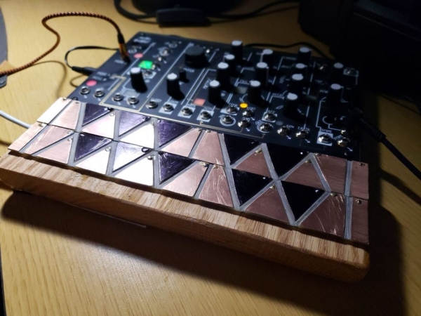
The only thing I’d change about the 0-Coast is that (Krell patches notwithstanding) it doesn’t have an on-board performance control. Most of the time it’s paired with an Arturia or a Korg, but my Keystep was so much wider than the 0-Coast that I found it a little unsatisfying. Buchla is often quoted saying he wanted to avoid “Black and white keys” because that forces you to think like a pianist instead of a synthesist essentially, and you can see the results in the controllers he came up with. Remembering that, I was inspired to create my own tribute to Don Buchla in the form of this capacitive-touch midi controller for my 0-Coast, “The Oceania.”
Step 1: Materials
The materials should be pretty familiar and easy to come by for any maker-it’s the process and time that are complicated. You’ll need:
Materials
1 Arduino Mega-I recommend the mini style (like this one at Amazon) to make it easier to mount under the sensor pads, but it’s not absolutely necessary. You might even be able to use an Uno/Genuino or Mini or Feather, but that would probably require you to treat the ADC pins as digital and I don’t know if the standard capacitance routine works on those. And you’d have to figure out the programming on your own.
2 220Ω resistors
1 Stereo 3.5mm phono socket
1 single sided sheet of copper clad (used for etching your own PCBs) at least 9″x2 3/4″
Stranded hookup wire (the thinner the better-I used this 30AWG, again from Amazon)
Solder
Something you like and are comfortable working with to mount it on
Stereo TRS 3.5mm male-to-male cable
Tools
A table saw (alternatively, a CNC or laser cutter would probably give you better results if you know what you’re doing.)
A soldering iron and soldering tools, including pliers, flush-cutters and wire strippers
A printer (paper, not 3-d)(but maybe also 3-d)
A straight-edge
A permanent marker/markers
A drill (a drill press or rotary tool press would be best.)
A Rotary Tool or file
Steel wool (optional)
Step 2: The Not-keys
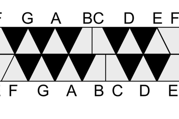
Print out the reversed (vertical) version of the pattern included (the one that doesn’t have any note letters on it) and cut the two rows into the right and left strips. Next, cut the copper clad into two strips the same size as the two strips of paper (each should be 8 7/8″ x 1 ⅛”.) Tape the paper strips to the backs of the pieces of copper clad and, using a permanent marker, mark the corners of the triangles, parallelograms and rectangles on the edges of the copper clad, then use a straight edge to connect them so that you have something that looks like the last photo with this step.
Next, very carefully set the table saw blade so that the blade barely cuts above the table level. The point is to remove a blade-width of the copper side of the clad but not cut through the fiberglass substrate (at least not substantially.) You may want to test it with some of the “drop” left over from cutting the strips of copper clad to see that the blade is neither too high nor too low. Cut the clad off using the lines drawn on the back as guides with which to line up the blade. You’ll want to use an angle guide with an extension. The diagonal lines should all be at 62.5˚. Go slowly. As you can see, my cuts didn’t quite come out as perfectly as I’d hoped. Once the channels are cut into the clad, you’ll want to file down any rough copper edges (blood would really mess with the capacitance after all.) I took some steel wool to mine to give it a brushed feel.
Needless to say, take all the usual precautions when working with a table saw. Wear safety glasses and use a push-stick, and FOR GOD’S SAKE IF YOU DON’T KNOW WHAT YOU’RE DOING DON’T EVEN TRY THIS!
Alternatively, I’ve included the PDF in hopes that if someone has a CNC machine or laser cutter they’d like to try this with that they can use the vectorized version of the layout and cut a professional looking one. (Please share the results if you do this.)
Once the not-keys are cut into the clad, drill holes with as small of a bit as your press can handle that will still allow you to get your hookup wire threads through into the tips or corners of the top rows of each of the not-key strips.
Of course if you want you could avoid the hassle and artistry and cut a traditional keyboard by cutting regular straight line grooves across one strip of clad and then cutting shorter, thinner strips to sit on top of those (as the #/♭keys.) Puffy double-stick tape will probably insulate enough that you wouldn’t trigger the notes underneath but that’s an untested conjecture. I’d be interested to see what you come up with.
Step 3: Electronics
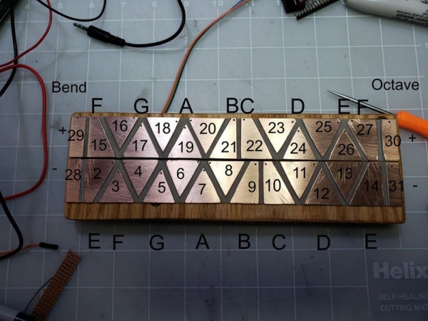
Solder one piece of hookup wire to each of the not-keys by running the wire through the drill holes from the back side, then flush-cut the wire off from the copper side. Without being too technical, think about how you’re going to mount it, and plan to make the wire just long enough to get from each not-key in each strip to the Arduino without having more than a couple mm of extra wire. Then, very carefully, one wire at a time, solder the wire from each not-key to to the Arduino Mega pin corresponding to the number marked on each not-key in the photo. This is the make-or-break part of the operation. You may wish to skip ahead to the programming part and test the function of the keys after every few solder connections. (For example on my original version, pin 13 bridged or something and always read as though it was being touched, so I had to write code to compensate and move everything above it down a pin value.)
Next, solder one 220Ω resistor between the +5v on the Arduino and the sleeve connector of the socket, and solder the other resistor between the Pin 1/TX pin and the tip connector of the socket. (Note that the pinouts for various sockets will vary so it’s up to you to determine which connection is which.) Finally, solder a piece of hookup wire between a Gnd pin on the Arduino to the ring connector on the socket.
As you can see I used a small piece of strip board to mount the resistors and socket, but that’s not absolutely necessary.
After soldering, you’ll want to file/sand/rotary-tool the flush cuts of the soldered wire until smooth enough to play, and you may choose to use permanent marker to color the not-keys in any configuration you choose. I made the downward facing triangles all black as a visual cue, but I tested a red and a silver permanent marker and each worked (silver oddly diminished the capacitance readings.)
Step 4: Mount It
Let’s not get too instruct-y about this part. Use whatever you feel comfortable with as a mount. I used stained solid oak for that classic synth look (a nod to the East Coast lineage) but you can use whatever you want. For example, I also made a CV version of this for my Eurorack case that’s mounted on a PVC sheet construction. You might consider 3D printing a base if you have access to a printer with a wide enough bed, or even making a cardboard base for it. It really doesn’t matter so long as it doesn’t interfere with the electronics.
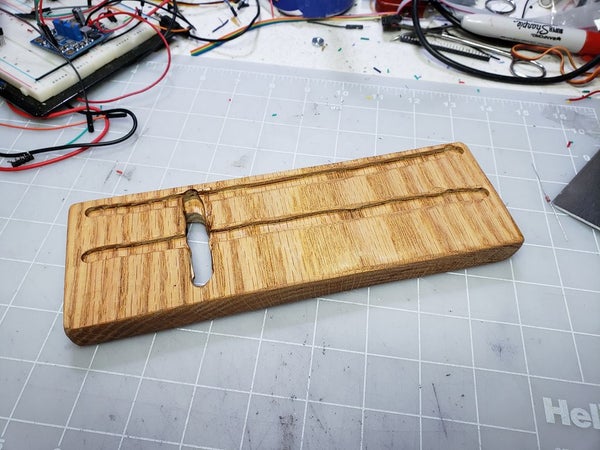
As you can see, I (sloppily) routed two channels for the wires on the backs of the not-keys, a recess for the electronics on the underside, and a port between the two so I could solder the wires to the copper clad pieces and the Arduino before mounting and simply pass the Arduino through the port. The piece of aluminum is what I used for mounting the electronics to (using plastic standoffs and a little hot glue for the socket strip board.) Then I screwed the metal into the base and put some EVA foot runners on the bottom.
The not-keys are attached to the base with strips of puffy double-stick tape, but again-use whatever you want as long as it doesn’t interfere with capacitance or circuitry.
Step 5: Program It
If you’ve never programmed an Arduino before then you’re on the right site-there are probably hundreds or thousands of ‘ibles on the subject, so I won’t cover that ground again.
In the attached zip file are two sketches. Download and unzip them and add them to your Arduino sketch library.
The first sketch(megaCapacitiveKeyboardTest) is an adaptation of the Arduino readCapacitivePin function which is here as a test that shows you what key is being pressed and the capacitance value for it while it’s being pressed in the serial monitor. It will let you see some values and test the connections from the Arduino to the not-keys.
Load this onto the Arduino, open the serial monitor (make sure to set the serial monitor to the correct baud) and touch a few not-keys, noting the values for the heaviest and lightest touch you’d be using to play. These will be used for the minCap (lightest touch) and maxCap (heaviest) values in the second sketch (OceaniaMidi_Release), which is what you will actually load onto the controller to use it as, well, a controller. If you need to adjust the values, do so, then save the sketch again and upload it to the Oceania.
Step 6: Play
The only power required to run the Oceania is sourced to the Arduino, so you can use the same cable as you used to upload the sketch and power it from your computer, or hook it up to a phone charger or a wall wart-whatever trips your fancy and works with the Arduino you used.
Plug the male-to-male cable into the Oceania socket and the Midi A socket of the 0-Coast or other compatible synth and have a go at it! The two keys to the far left (pins 29/28) act as pitch bend and the two to the far right (pins 30/31) will raise and lower the octave the notes are sent as.
The 0-Coast seems to have a tendency to hang onto some notes sent by the Arduino, but usually you can just touch the hanging tone again and it will turn off. Also if the 0-Coast is connected to the Oceania when you load the sketch it may get stuck on a low note. If that happens just power cycle the 0-Coast and it should go away.
Finally, it occurs to me that one thing that would have made the cutting of the copper clad much cleaner would have been a laser cutter, so if you found this at all helpful, please vote for this Instructable in the Epilog X contest.
Source: Oceania Midi Controller (for Make Noise 0-Coast and Other Synths)