Summary of Objective of the Experiment: Arduino Microcontrollers Applications with Switches and Sensors
Summary: This lab introduces Arduino Uno basics: setting up the board and software, uploading example sketches, reading digital and analog inputs (pushbutton, potentiometer), controlling outputs (LEDs, speaker), using pinMode/digitalRead/digitalWrite/analogRead, generating tones with tone(), and creating custom sketches to react to sensor input. Students build circuits, measure voltages, modify example sketches, and record results.
Parts used in the Arduino Switches and Sensors Lab:
- Two 1 kΩ resistors
- One 100 kΩ potentiometer
- One Arduino Uno
- One USB cable
- Debounced pushbutton (on proto-board)
- Proto-board with Logic Indicator and switches (5V/+V and TTL/CMOS)
- Speaker
- Digital Multimeter (DMM)
- Oscilloscope
- 150 Ω resistor (optional, substitute for 1 kΩ if tones are quiet)
I. Objective
The main goal of this experiment is to familiarize oneself with the utilization of the Arduino microcontrollers for monitoring switches and sensors. Additionally, the objective is to trigger devices like LEDs or a speaker based on specific sensor output values.
II. List of Needed Components
The following components are necessary for conducting this experiment:
- Two 1 kΩ resistors
• One 100 kΩ potentiometer
• One Arduino Uno
• One USB cable
III. Background
The Arduino is a versatile microcontroller board with the capability to read switches and sensors and control various devices like lights, speakers, motors, and more. Microcontrollers find applications in a wide range of devices such as cars, cell phones, cameras, appliances, printers, etc. One of their many functionalities includes monitoring sensors and triggering an output device based on specific conditions. For instance, in a motion-controlled light setup, a microcontroller might activate a light when motion is detected by a motion sensor and then turn it off after a set period. Microcontrollers are commonly used to oversee sensors and manage motors or actuators in robots, quadcopters, and similar applications.
On the Arduino website (www.arduino.cc), you can find comprehensive information about the Arduino Uno and its programming procedures. If you wish to download the free Arduino software, simply click on the “Software” section. For technical specifications concerning the Arduino Uno board, navigate to “Products,” then “Arduino,” and click on “Uno.” To enhance your understanding of Arduino programming, you can explore the “Learning” and “Reference” sections. Additionally, you’ll find tutorials, a forum, a collection of Arduino projects, and more. It’s important to note that no prior programming experience is required to successfully complete this lab.
IV. Prelab Assignment
- What does the Arduino command “pinMode” do?
- What does the Arduino command “digitalWrite” do?
- What does the Arduino command “digitalRead” do?
- What does the Arduino command “analogRead” do?
V. Procedure
Part 1: Arduino Set Up
In this section of the experiment, we will utilize a pre-existing sketch to create a blinking effect for an LED. To program the Arduino microcontroller, we’ll employ the free Arduino software, a text editor that enables us to write programs referred to as sketches (refer to Figure 1).
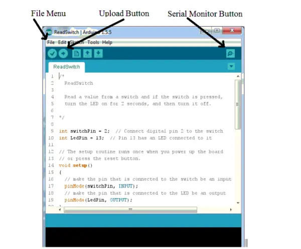
Begin by connecting the Arduino board to the computer using the USB cable. Once connected, open the Arduino software. Within the software, you’ll find several example sketches provided. To access the “Blink” example sketch, click on File, then go to Examples, 01.Basics, and select Blink. The Blink sketch will then open in a new Arduino window.
Set up the software for the Arduino Uno board by following these steps:
1. Click on Tools, then select Board, and choose Arduino/Genuino Uno.
2. Click on Tools again, then select Port, and choose the port labeled as “Arduino/Genuino Uno.”
3. In case you don’t see any ports with the label “Arduino/Genuino Uno,” attempt unplugging the Arduino from the computer and then plug it back in.
To execute the sketch, click on the Upload Button (refer to Figure 1). This action will initiate the compilation, upload, and execution of the sketch. Upon completion, the LED located near pin 13 should exhibit a repeating pattern of turning on for 1 second, followed by turning off for 1 second. If you encounter an error message like “Problem uploading to board,” you can resolve it by selecting another port. Simply click on Tools, then Port, and choose a different port from the list.
Part 2: Blink Sketch
Now, let’s explore the Blink sketch and customize it to blink in a pattern of your preference. While the Arduino board is programmed using the C++ computer language, the Arduino software incorporates various features that allow you to create sketches without requiring an in-depth knowledge of C++.
The text located at the beginning of the Blink sketch serves as a comment. Comments are utilized to document the sketch, providing insights for individuals who read or edit it. However, it’s important to note that comments are ignored by the Arduino software during the compilation process. Two methods exist to designate text as a comment. Firstly, if a line contains the characters “//”, everything following it is considered a comment. Secondly, any text enclosed between “/*” and “*/” is treated as a comment.
The “setup” function is responsible for initializing the sketch. This function is executed only once, either when the Arduino board is powered up for the first time or when it is reset using the reset button.
The Arduino Uno offers 14 general-purpose input/output (I/O) pins, which can be configured as either inputs or outputs. Pin 13 is connected to an LED on the Arduino board. To set pin 13 as an output, the command “pinMode(LED_BUILTIN, OUTPUT)” is used. This works because the Arduino software assigns the value 13 to LED_BUILTIN. By replacing LED_BUILTIN with any other pin number, you can set any pin as an output. Similarly, to set a pin as an input, replace OUTPUT with INPUT. Remember to include a semicolon “;” after each command, and the commands within a function are enclosed in curly brackets “{ }”.
Once the “setup” function finishes its execution, the “loop” function is continuously called by the Arduino until either the board is powered down or reset. Within this sketch, the command “digitalWrite(LED_BUILTIN, HIGH)” is used to set Pin 13 to a HIGH state, resulting in the pin outputting +5V and turning on the LED. You can set any pin to a HIGH state by replacing LED_BUILTIN with the respective pin number. The “delay(1000)” command introduces a pause of 1000 milliseconds (1 second). Subsequently, the command “digitalWrite(LED_BUILTIN, LOW)” sets Pin 13 to 0V, turning off the LED. After another 1000 milliseconds pause, the “loop” function is invoked again, repeating the entire process.
Part 3: Blink LEDs
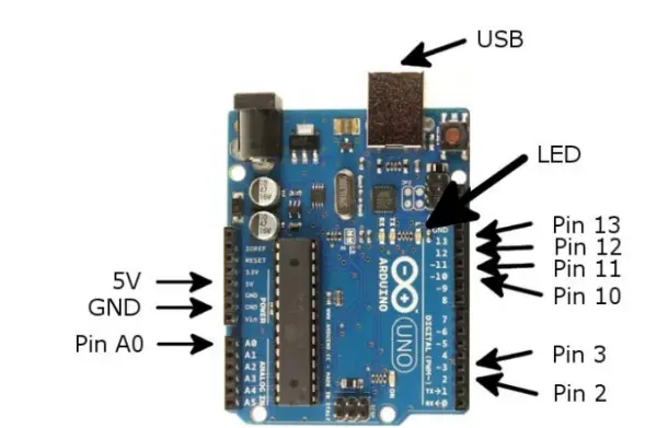
Build the circuit as depicted in Figure 2. Ensure that the center connector (Pin 2) of the potentiometer is connected to Arduino Pin A0, as illustrated in Figures 3 and 4. Regarding the Debounced Pushbutton, it is internally connected to ground, so there is no need to make that connection manually. Additionally, please be aware that the Arduino pin labeled as “5V” serves as a power supply specifically generated on the Arduino board for this experiment. Do not connect the bench supply or the Proto-board supply to the Arduino; instead, utilize the provided power supply on the board.
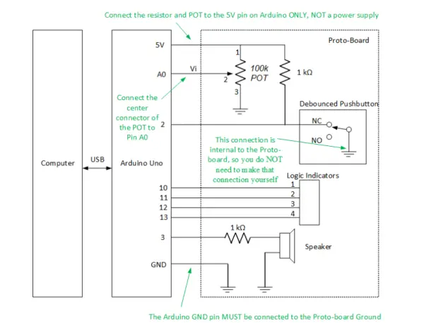

To ensure proper functionality of the Debounce Pushbutton circuit, make sure to power on the Proto-board. Within the Logic Indicator section on the Proto-board, locate a switch labeled “5V/+V” and set it to the “5V” position. Additionally, there is another switch labeled “TTL/CMOS”; set this switch to “TTL.”
Verify the functionality of your circuit by utilizing the Digital Multimeter (DMM) to measure the voltage connected to Arduino Pin 2. When the button is not pressed, the measured voltage should be 0V, and when the button is pressed, it should read 5V. Similarly, the voltage connected to Arduino Pin A0 should fluctuate between 0V and 5V as you turn the knob on the potentiometer. It is crucial to remember that Arduino input pins must never be connected to a voltage higher than 5V or lower than 0V, as doing so could potentially harm the Arduino board.
Create a backup of the Blink sketch by selecting File and then Save As, and save it to your P: drive. Afterward, customize the sketch to make the four Logic Indicator LEDs blink in a pattern according to your preference. Once you’ve made the modifications, save the updated sketch to your P: drive.
Part 4: Read a Digital Input
In this section, we will explore an example sketch that demonstrates reading a digital input. This sketch can be adapted to monitor various sensors, including motion detectors, which provide a digital output. To access the example sketch named “DigitalReadSerial,” click on File, go to Examples, select 01.Basics, and then choose DigitalReadSerial.
To execute the sketch, compile, upload, and run it by clicking on the Upload button. Afterward, click on the Serial Monitor button (refer to Figure 1). The sketch is expected to print “0” to the Serial Monitor when the button is not pressed and “1” when the button is pressed.
Now, let’s take a closer look at the DigitalReadSerial sketch. The line “int pushButton = 2” establishes a variable named “pushButton” with a value of 2. This variable is of type “int,” allowing it to store only integer values. Since this variable is defined outside of any function, it is considered global, making it accessible from any function within the sketch. The purpose of this variable is to store the input pin number to which the pushbutton switch is connected.
Within the “setup” function, the command “Serial.begin(9600)” is employed to establish a serial connection (transmitting data one bit at a time) with the computer at a rate of 9600 bits per second. This command is essential for printing out any values in the sketch. The “pinMode(pushButton, INPUT)” command initializes Pin 2 as an input. It’s worth noting that when the Arduino powers up, the I/O pins are automatically set as inputs, making this particular command technically unnecessary.
Within the “loop” function, the line “int buttonState = digitalRead(pushButton)” establishes an integer variable named “buttonState.” Variables defined inside a function are private to that function, making them only accessible to other commands within the same function. The “digitalRead” function is used to read the value from Pin 2, and the outcome is stored in the variable “buttonState.” When the voltage on the input pin is close to 5V, the “digitalRead” function returns the value 1; otherwise, it returns 0.
The “Serial.println(buttonState)” command is used to display the value of the variable “buttonState” on the Serial Monitor. The “delay(1)” command introduces a 1 millisecond delay. The “loop” function is continuously called until the power is turned off or the Arduino is reset.
Make a duplicate of the DigitalReadSerial sketch and save it to your P: drive by selecting File and then Save As.
Let’s enhance the sketch to perform different actions based on whether the switch is pressed or not. Add the following lines within the “loop” function after the “digitalRead” line: [Instructions to add new lines here].
if (buttonState == 0) // if switch is not pressed (note there are two equal signs)
{
digitalWrite(13, LOW); // turn LED off
}
else
{
digitalWrite(13, HIGH); // turn LED on
}
Test the aforementioned modification. Observe that the LED connected to Pin 13 should be off when the switch is not pressed and on when the switch is pressed.
Now, further modify the sketch to make the LEDs blink in two different patterns based on whether the switch is pressed or not. After making these modifications, save your updated sketch to your P: drive.
Checkpoint 1:Demonstrate your sketch to the instructor
art 5: Read an Analog Input
In this section, we will explore a sketch that reads an analog input voltage from a potentiometer. This sketch can also be adapted to monitor various sensors, such as an RTD or photosensor, which provide analog outputs. To access the example sketch named “AnalogReadSerial,” click on File, go to Examples, select 01.Basics, and then choose AnalogReadSerial.
Click on the Upload button, and then click on the Serial Monitor button (refer to Figure 1). While adjusting the potentiometer knob, observe the voltage Vi in Figure 2, which should vary between 0 and 5V. The printed values on the Serial Monitor will also fluctuate accordingly. Determine the relationship between the voltage Vi and the values displayed in the Serial Monitor.
The Analog ReadSerial sketch initializes the serial connection to the computer at 9600 bits per second within the “setup” function. In the “loop” function, the sketch employs the analogRead command to read the analog voltage from pin A0, thereby converting it into an integer. This integer value is stored in the variable “sensor Value,” which is then printed to the Serial Monitor, followed by a 1 mS delay.
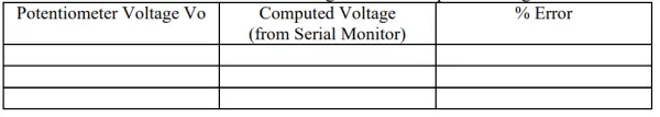
Create a duplicate of the Analog Read Serial sketch and save it to your P: drive by selecting File and then Save As. Next, modify the sketch to convert the value returned from the analog Read function into volts and print out the voltage value. To store the value in volts, you will require an additional variable capable of storing floating-point numbers, so instead of using “int,” use “float” as the variable type. Additionally, when calculating the voltage, ensure that you instruct the Arduino to use floating-point arithmetic by employing constants with decimal points (e.g., 5.0 and 1023.0) instead of integer values (5 and 1023). Run your sketch and record both the voltage Vi and the voltage computed by your program (see Table 1). Finally, compute the percentage error. Save your modified sketch to your P: drive.
Part 6: Making Tones
In this section, we will create a new sketch to produce tones with a speaker. To begin, open a new sketch by clicking on File and then New. Afterward, manually type or copy and paste the following sketch into the Arduino software.
/*
* Generate Tones
*/
int speakerPin = 3; // pin connected to the speaker
void setup()
{
// put your setup code here, to run once:
pinMode(speakerPin, OUTPUT); // set speakerPin to output
}
void loop()
{
// put your main code here, to run repeatedly:
int i; // loop counter
int frequency = 500; // frequency in Hz
int duration = 250; // duration in mS
int shortDelay = 500; // short delay time in mS
for (i = 0; i < 3; i++)
{
// generate tone
tone(speakerPin, frequency, duration);
delay(shortDelay); // short delay
}
delay(5000); // long delay
}
Execute the sketch and if the tones are too quiet, replace the 1 kΩ resistor in series with the speaker with a 150 Ω resistor. However, ensure that you do not decrease the resistance below 150Ω as it may damage the Arduino.
The tone function requires three arguments: the pin number connected to the speaker, the frequency of the tone in Hz, and the duration of the tone in milliseconds.
The “for” command, also known as a for loop, repeats the tone and delay functions three times. The for loop consists of three commands enclosed in parentheses. The first command, “i = 0,” is executed only once at the beginning of the loop to initialize the loop counter. The second command, “i < 3,” serves as a test, and if the condition is true, the statements within the parentheses are executed. Then, the third command, “i++,” increments the value of the loop counter by 1 in this case. This process continues until the test condition becomes false, after which the sketch proceeds to the commands following the loop.
As a result, the “for” command is equivalent to the following commands:
i = 0; // initialize counter variable (this command is executed only once)
i < 3; // this test is true, so do the loop commands
tone(speakerPin, frequency, duration); // generate tone
delay(delayTime); // delay
i++; // increment loop counter, so now i equals 1
i < 3; // this test is true, so do the loop commands
tone(speakerPin, frequency, duration); // generate tone
delay(delayTime); // delay
i++; // increment loop counter, so now i equals 2
i < 3; // this test is true, so do the loop commands
tone(speakerPin, frequency, duration); // generate tone
delay(delayTime); // delay
i++; // increment loop counter, so now i equals 3
i < 3; // this test is now false, so skip down to the commands after the loop
Establish a connection between the oscilloscope and Arduino Pin 3 to measure the period of the generated tones. Draw a sketch of the oscilloscope display and label the period, as well as the maximum and minimum voltages. Next, calculate the fundamental frequency and the percentage error in comparison to the frequency specified in the “tone” command.
Afterward, customize the sketch to play tones according to your preferences. Once the modifications are complete, save your updated sketch.
Part 7: Explore
Develop a sketch that monitors a switch, potentiometer, or sensor, and utilize the input from these components to activate LEDs and/or the speaker in various ways.
VI. Conclusion
In this lab, we have explored the capabilities of Arduino, which is a versatile microcontroller board. Arduino allows us to interact with various components, such as switches, potentiometers, and sensors, enabling us to control LEDs, speakers, motors, and more. Arduino is programmed using the Arduino software, which lets us write sketches to define the behavior of our projects. The board has both digital and analog input/output pins, with analog voltages represented using a range from 0 to 5 volts. Additionally, we have learned how to read analog voltages from sensors using the analogRead function and to output audio tones and signals through the speaker using the tone function. With Arduino’s flexibility and wide range of applications, it serves as a valuable tool for creating diverse electronic projects and automation tasks.
Checkpoint 2:Present your conclusion and showcase the sketch you created in Part 7 to the instructor.
- What does the Arduino command pinMode do?
It initializes a specified pin as either INPUT or OUTPUT so the pin behaves accordingly. - What does the Arduino command digitalWrite do?
It sets a digital output pin to HIGH (+5V) or LOW (0V), for example turning an LED on or off. - What does the Arduino command digitalRead do?
It reads the digital state of an input pin and returns 1 when the voltage is near 5V and 0 otherwise. - What does the Arduino command analogRead do?
It reads an analog voltage on an analog input pin (such as A0) and returns an integer value representing that voltage. - How do you upload and run an example sketch like Blink?
Open the Blink example in File > Examples > 01.Basics > Blink, select Board Arduino/Genuino Uno and the correct Port under Tools, then click Upload. - Can you use the Arduino built-in 5V supply for the proto-board?
Yes; the lab instructs to use the Arduino 5V pin and not an external bench or proto-board supply. - How can you make tones with the Arduino?
Use the tone function with arguments pin, frequency in Hz, and duration in ms; adjust series resistor if tones are too quiet. - What should you check to verify the debounced pushbutton circuit?
Use the DMM to confirm Pin 2 reads 0V when not pressed and 5V when pressed, and ensure proto-board switches are set to 5V and TTL. - How do you convert analogRead results to volts in a sketch?
Use a float variable and floating-point constants like 5.0 and 1023.0 to compute voltage from the analogRead integer value.