
Summary of Nick Smith – Magical Music Box using arduino
This project, the Magical Music Box, transforms audio input into a dynamic light show. A microphone captures sound, which is then amplified and filtered into three frequency bands using operational amplifiers and a potentiometer for sensitivity control. The Arduino processes these signals to drive four RGB LEDs, creating a visual response synchronized with the music, all powered by dual 9V batteries.
Parts used in the Magical Music Box:
- 1x arduino
- 8x 1k ohm resistors
- 5x 10k ohm resistors
- 7x 560 ohm resistors
- 3x 150 ohm resistors
- 1x large potentiometer
- 4x RGB LED's
- 8x .1 uF capacitors
- 2x LM358N op amps
- 1x LM386 op amp
- 1x microphone sensor
- 2x 9v batteries with battery holders
- approx 2 miles of wire
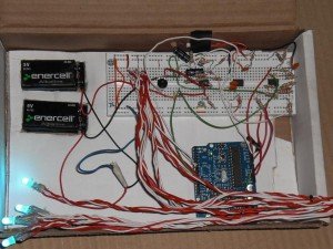
This is my Magical Music Box which converts music into a light show. When i was daydreaming what to make for my final project, i wanted something that would make a light show for any song simply by hearing it.
Materials used:
1x arduino
8x 1k ohm resistors
5x 10k ohm
7x 560 ohm
3x 150 ohm
1x really really really big potentionmeter. so big its basically an on/off switch….
4x RGB LED’s
8x .1 uF capacitors
2x LM358N op amps
1x LM386 op amp
1x microphone sensor
2x 9v batteries with battery holders
approx 2 miles of wire
some kicking music to show off with
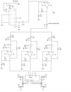
Real simply, i used a microphone circuit for input, amplified it, ran it threw a potentiometer so i could control how senstive it was to ambient noise then split it into 3 band pass filters to tune out other frequencies then used that as an input for my arduino. A simple conditional based on that input controlled 6 digital out pins with each pin connected to a single input on 2 separate red, green, blue LED’s. So since each LED has 3 inputs, thats 6 pins to control 4 RGB LED’s.
I ran everything off of 2 nine volt batteries, one as +9v and the other as -9v. Here is a simple power schematic to be used in conjunction with the schematic above. I used the arduino for all my grounds.
Now for the gritty details. I used the PDF titled Op Amps for Everyone, which i have included a copy of at the end of this post, to learn how to make a band pass filter. Specifically i used the Sallen Keys band pass filter located in section 16.5.1.1
For more detail: Nick Smith – Magical Music Box
- How does the device convert music into a light show?
A microphone circuit captures input, amplifies it, filters it into three bands, and sends the data to an Arduino that controls digital output pins connected to RGB LEDs. - Can I adjust the sensitivity to ambient noise?
Yes, a large potentiometer is used in the circuit to control how sensitive the system is to ambient noise. - What components are used to tune out other frequencies?
The project uses three band pass filters created with operational amplifiers to tune out specific frequencies. - Does the project require AC power or batteries?
The system runs off two nine volt batteries, with one serving as +9v and the other as -9v. - How many RGB LEDs are controlled by the Arduino?
The Arduino controls four RGB LEDs using six digital output pins, where each pin connects to a single input on the LEDs. - What resource was used to design the band pass filter?
The author used the PDF titled Op Amps for Everyone, specifically the Sallen Keys band pass filter located in section 16.5.1.1. - How are the grounds handled in the schematic?
The author used the Arduino for all grounds in the circuit setup. - What is the role of the LM386 component?
The LM386 is one of the operational amplifiers used in the circuit to amplify the microphone signal.