This Instructable describes a lower-cost, battery-powered wireless IOT sensor layer for my earlier Instructable: LoRa IOT Home Environmental Monitoring System. If you haven’t already viewed this earlier Instructable, I recommend reading the introduction for an overview of the capabilities of the system which are now extended to this new sensor layer.
The original LoRa IOT Home Environmental Monitoring System achieved the objectives I had set out when it was published in April 2017. However, after using the monitoring system for a number of months to monitor temperature & humidity on each floor of the house, I wanted to add 11 more sensors at particularly vulnerable locations in the house; including, six sensors strategically placed in the basement, sensors in each bathroom, and a sensor in the attic, laundry, and kitchen.
Rather than add more LoRa based sensors from the earlier Instructable which are somewhat expensive and powered via AC adapters, I decided to add a layer of lower cost, battery operated sensors using 434-MHz RF Link Transmitters. To maintain compatibility with the existing LoRa IOT Home Environmental Monitoring System, I added a wireless bridge to receive the 434-MHz packets and retransmit them as LoRa packets at 915-MHz.
The new sensor layer consists of the following subsystems:
- 434-MHz Wireless Remotes – battery operated temperature and humidity sensors
- Wireless Bridge – Receives 434-MHz packets and retransmits them as LoRa packets.
The 434-MHz Wireless Remotes use lower transmit power and less robust protocols compared with LoRa radios, so the Wireless Bridge location in the house is chosen to ensure reliable communication with all 434-MHz Wireless Remotes. Using the Wireless Bridge allows communication with the 434-MHz Wireless Remotes to be optimized without placing any constraint on where the LoRa IOT Gateway is located.
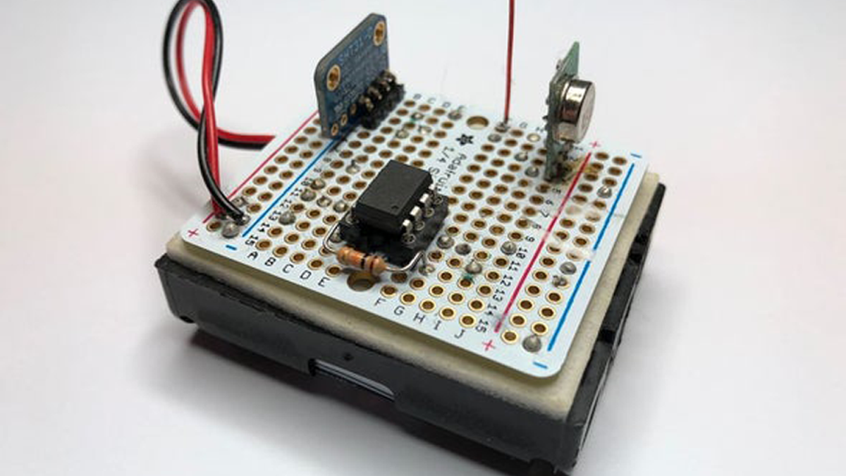
The 434-MHz Wireless Remotes and Wireless Bridge are built using readily available hardware modules and a few individual components. The parts can be obtained from Adafruit, Sparkfun, and Digikey; in many cases, Adafruit and Sparkfun parts are also available from Digikey. Competent soldering skills are needed to assemble the hardware, in particular, the point-to-point wiring of the 434-MHz Wireless Remotes. The Arduino code is well commented for understanding and to enable easy extension of functionality.
The objectives for this project included the following:
- Find a lower cost wireless technology suitable for household environments.
- Develop a battery powered wireless sensor able to operate for a number of years on one set of batteries.
- Require no modification to the LoRa IOT Gateway hardware or software from my earlier Instructable.
The total parts cost for the 434-MHz Wireless Remotes, excluding the 3xAA batteries, is $25, of which the SHT31-D temperature and humidity sensor accounts for more than half ($14).
As with the LoRa remotes from my earlier Instructable, the 434-MHz Wireless Remotes take temperature and humidity readings, and report to the LoRa IOT Gateway, via the Wireless Bridge, every 10 minutes. The eleven 434-MHz Wireless Remotes were put into operation in December 2017 using 3 x AA batteries nominally providing 4.5V. The battery readings from the eleven sensors in December 2017 ranged from 4.57V to 4.71V, sixteen months later in May 2019 the battery readings range from 4.36V to 4.55V. The use of parts with a wide operating voltage range should ensure operation of the sensors for another year or more, subject to maintaining RF link reliability as transmit power is reduced with lower battery voltages.
The reliability of the 434-MHz sensor layer has been excellent in my household environment. The new sensor layer is deployed across 4,200 SqFt of finished space and 1,800 SqFt of un-finished basement space. Sensors are separated from the Wireless Bridge by a combination of 2 – 3 interior walls and floor/ceilings. The LoRa IOT Gateway from my earlier Instructable sends an SMS Alert if communication is lost with a sensor for more than 60 minutes (6 missed ten minute reports). One sensor, on the floor in a corner at the far end of the basement behind stacked boxes, will cause a lost contact alert every now and then, however, in all cases communication with the sensor re-establishes without any intervention.
Thank you for visiting this instructable, and please see the following steps for further information.
- Battery Operated Wireless Sensor Design
- 434-MHz Wireless Remote Hardware
- 434-MHz Wireless Remote Software
- Wireless Bridge Hardware
- Wireless Bridge Software
Step 1: Battery Operated Wireless Sensor Design
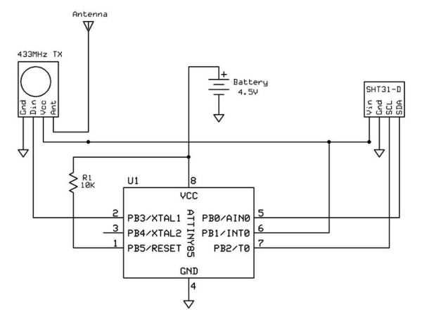
The design for the 434-MHz Wireless Remote uses the following parts:
- ATtiny85 8-bit AVR Microcontroller
- Sensirion SHT31-D – Temperature & Humidity Sensor Breakout Board
- Sparkfun 434-MHz RF Link Transmitter
- 10K Ohm resistor
One of the early design decisions was to avoid devices that require regulated 3.3V or 5V, and select parts that operate over a wide voltage range. This eliminates the need for voltage regulators which are power wasters in a battery operated design, and extends operating life of the sensors as they will continue to function longer as battery voltage declines over time. The operating voltage ranges for the parts chosen are as follows:
- ATtiny85: 2.7V to 5.5V
- SHT31-D: 2.4V to 5.5V
- RF Link Tx: 1.5V to 12V
Allowing for some margin, the 434-MHz Wireless Remotes should functionally operate down to a battery voltage of 3V. As already noted, it just remains to be seen how well RF link reliability is maintained as transmit power is reduced with lower battery voltages.
The decision was made to use 3 x AA batteries to provide a nominal starting voltage of 4.5V. After 16 months of operation, the lowest battery voltage measured is 4.36V.
The ATtiny85 Watch Dog Timer (WDT) is used to keep the 434-MHz Wireless Remote in a Sleep mode for most of the time. The ATtiny85 is woken up by the WDT every 8 seconds to increment a 10 minute counter; upon reaching a 10 minute interval, a measurement is taken and a data packet transmitted.
To further minimize power consumption, the SHT31-D and RF Link Transmitter are powered from a digital I/O port pin on the ATtiny85 configured as an output. Power is applied when the I/O pin is driven High (1), and removed when the I/O pin is driven Low (0). Through software, power is only applied to these peripherals every 10 minutes for 1 – 2 seconds while measurements are being taken and transmitted. Refer to 434-MHz Wireless Remote Software for description of the related software.
The only other component used in the 434-MHz Wireless Remote is a 10K ohm resistor used to pull up the Reset pin on the ATtiny85.
An early design used a resistive voltage divider across the battery to enable an ADC pin on the ATTINY85 to measure battery voltage. Although small, this voltage divider placed a constant load on the battery. Some research turned up a trick that uses the ATtiny85 internal 1.1V band gap reference voltage to measure Vcc (battery voltage). By setting the ADC reference voltage to Vcc and taking a measurement of the internal 1.1V reference voltage, it is possible to solve for Vcc. The ATtiny85 internal 1.1V reference voltage is constant as long as Vcc > 3V. Refer to 434-MHz Wireless Remote Software for description of the related software.
Communication between the ATtiny85 and SHT31-D is via I2C bus. The Adafruit SHT31-D breakout board includes pull-up resistors for the I2C bus.
Communication between the ATtiny85 and the RF Link Transmitter is via a digital I/O pin configured as an output. The RadioHead Packet Radio library RH_ASK is used to On-Off Key (OOK / ASK) the RF Link Transmitter via this digital I/O pin.
Read more: New Wireless IOT Sensor Layer for Home Environmental Monitoring System