There are several situations where using an RTC could adversely affect your project by increasing cost, size, time accuracy or IO requirements. To prevent this, especially in ESP/WiFi-based or other clock-reliant projects, makers usually turn to obtain time information from NTP servers. I recently came across a project by BitsandBlobs which used standalone NTP Servers and I felt it might be one of the best ways to introduce to this concept. So for today’s tutorial, we will build an NTP Based Network Time Clock based on “BitsandBlobs” build.
NTP (Network Time Protocol) is an internet protocol used for synchronizing clocks on computer networks within a few milliseconds of universal coordinated time (UTC). Using this protocol, devices can request and receive UTC data from an NTP server which usually receives precise time from an atomic clock.
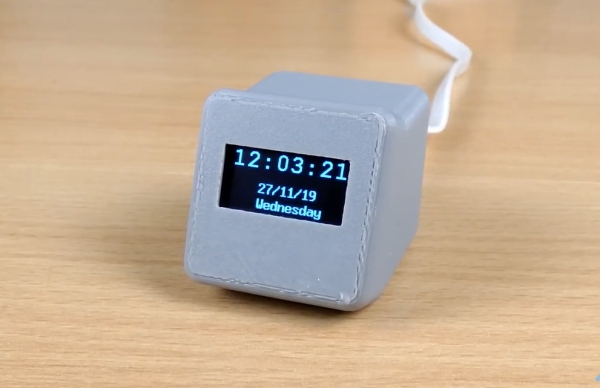
The WiFi capabilities of the ESP8266 based Wemos D1 mini will be used in obtaining time information from a public NTP server and it will be displayed in a user-friendly manner on an OLED display.
At the end of this project, you would know not only how to obtain time information from NTP servers, but also how to use the WemosD1 for your WiFi projects.
REQUIRED COMPONENTS
The following components are required to build this project:
- Wemos D1 Mini
- 0.96″ I2C OLED Display
- Jumper Wires
- BreadBoard (Optional)
The components can be purchased from the attached links. While an interesting enclosure was built for this project, for those who don’t have access to a 3D printer and don’t want to solder the components, you can go for the option of implementing the project on a breadboard.
SCHEMATICS
Thanks to the use of just two components, the schematics for today’s project is super straightforward. The OLED display being used communicates with the host microcontroller via I2C as such all we need do is connect the display to the I2C pins of the Wemos D1 mini as shown in the schematics below:
To make the connections easier to follow, a pin-pin map is provided below:
Wemos D1 – OLED
D1 - SCL
D2 - SDA
5v - VCC
GND - GND
It is important to note the maximum input voltage of your OLED display and be sure it is 5V tolerant. You should connect the VCC pin of the OLED to the Wemos D1’s 3.3v pin if 5V is too high for the display.
Read more: NETWORK CLOCK USING ESP8266 AND OLED DISPLAY