In this Instructable, we will describe how to turn a “retro” oil lamp into a NeoPixels based rechargeable lamp with colorful light effects.
Supplies
- Arduino nano
- 12 bits NeoPixel ring
- Micro USB 5V 1A TP4056 Lithium battery charger module
- 3.7V 9800mAh Lipo Li-polymer Battery
- Rotary encoder Ec11 or KY-040 Module
- Self-locking square button switch
- An Oil Burning Lantern (https://www.amazon.com/Dietz-76-Original-Oil-Burning-Lantern-Red/dp/B00MFU0XGO/ref=cm_wl_huc_item)
- Eight 3D printed parts (please find the STL links)
Step 1: Disarm the Wick Mechanism.
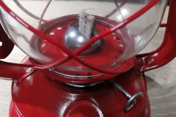
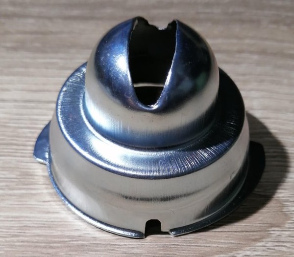
Remove the glass jar by pulling the top of the lamp (as seen in the first and second photo), and then remove the wick holder (third and fourth photo).
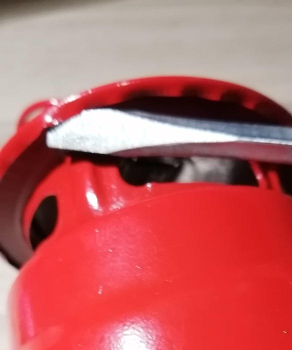
Remove the wick adjustment mechanism by unfolding the foil tabs (fifth photo).
Cut the knob wire just near the cogwheel.
Step 2: The Encoder Support.
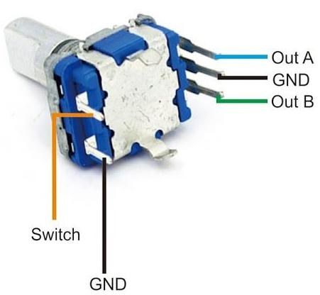
Identify the encoder pins as shown in the first photo. Solder a wire between the two pins marked as GND (third photo).
Solder a cable on each one of the pins (out A, out B, switch, and one of GND) we suggest mark the end of the cables in order to identify the encoder pins.
Attach the 3D printed coupling in the encoder knob (sixth photo).
Insert the wick knob in the 3d printed encoder support (maybe you would need to adjust the hole so the wick knob wire can rotate freely (see the seventh photo).
Insert and glue the wick knob in the 3D printed coupling as shown in the eighth photo.
Glue the encoder to it’s placed in the support (ninth and tenth photo).
Step 3: Replace the Wick Mechanism for the Encoder Support.
Use a rotating tool to enlarge the knob notch, so the module constructed in Step 2 can fit in the top of the piece and glue it (be sure that the knob can rotate freely).
Step 4: Wiring and Fitting of the NeoPixel Ring.
Solder a wire in each Di, 5V, and GND contacts of the NeoPixel ring. It’s a good idea to mark the end of the cables with a color in order to identify them.
Glue the NeoPixel ring to the 3d printed isolator and glue it in its place in the lamp as shown in the photos.
Step 5: The Switch
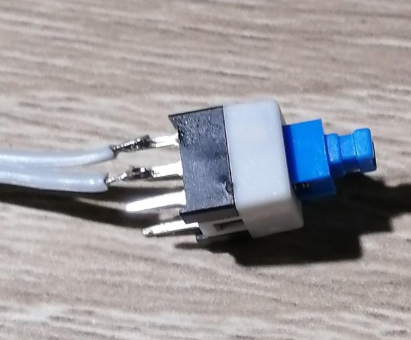
Solder two wires to the switch contacts. Pass the wires through the 3d printed support and glue the switch as shown in the photos above.
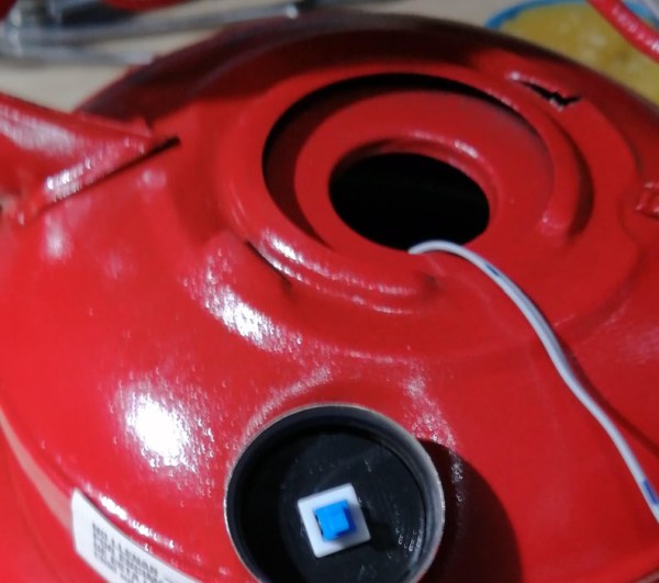
Remove the plastic seal in the oil tank and pass the wires through the hole and glue the support. Take the cables out through the wick hole.
Drill a hole in the oil tank cap’s bottom to avoid activating the switch when screwing on the cap.
Step 6: Mounting the Charger
Remove the chimney cover with the help of a screwdriver, taking care not to mistreat the paint.
Pull the chimney out up to the top, and drill a hole in the lowest chimney’s side, as shown in the third photo.
Take 40 cm of four ways ribbon cable and mark both ends of the first and fourth with red and black in order to identify these, as shown in the fourth photo.
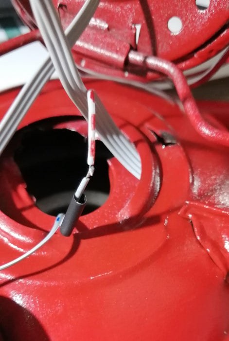
Now, get yourself a lot of patience! The goal is to pass the ribbon cable through the right lamp’s arm all the way to the top. Push the ribbon cable as shown in the fifth photo. Push it slowly and firmly up to when the ribbon cable comes to the top and pass through the hole that you drilled in the chimney’s side (see the sixth photo).
Protect the ribbon cable with a 5cm Thermofit’s piece passing it through the chimney’s side hole, as shown in the three last photos.
Step 7: Wiring and Mounting the Charger
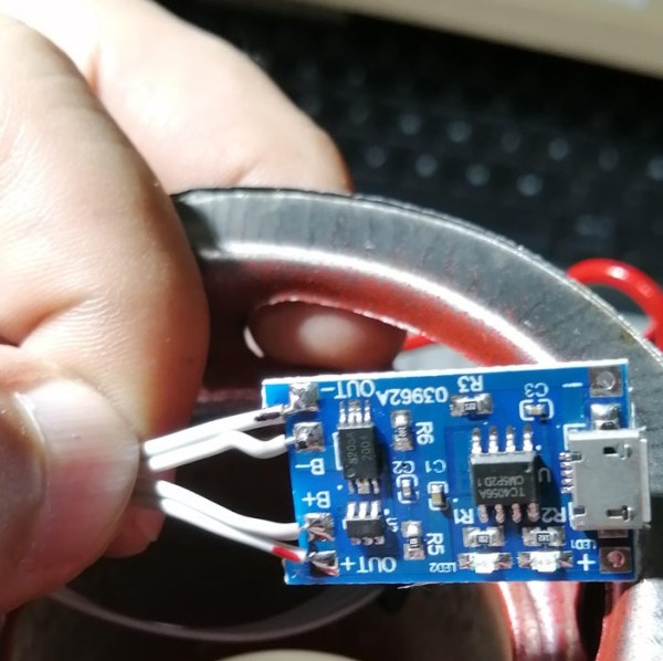
Solder the upper extreme of the ribbon cable as shown in the first picture; the cable marked in black at the “out -” pin, the following at the “B -“, the next at “B +” and the last one (marked in red) at “out +” pin. The inner two cables (“B -” and “B +”) will be connected to the battery later.
Mount and glue the charger in the 3d printed support as shown in the second and third photo. Glue the support to the chimney as shown. Glue the 3d printed lid.
Put back the chimney cap by bending the foil to fit it.
Step 8: Prepare the Oil Tank
Sand the supports of the wick mechanism in the oil tank in order to solder the encoder cover mounted in Step 3.
Enlarge the oil tank hole by making two cuts so that the battery can pass through. Fold the foil inside the tank to avoid sharp edges.
Step 9: Wirng the Arduino
Solder the red marked cable (from the OUT+ charger pin) to one of the switch cables. Isolate it with Thermofit.
Pass the NeoPixel ring cables through the encoder cover.
Make the connections following the diagram.
Step 10: Wiring the Battery
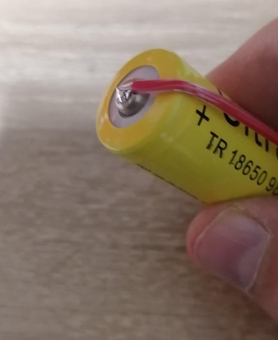
Solder a cable in each pole of the battery and isolate them with tape.
Step 11: Almost Finish!
Solder the battery cables to their corresponding ones from the charger (B+ and B-). Isolate each one with tape or Thermofit.
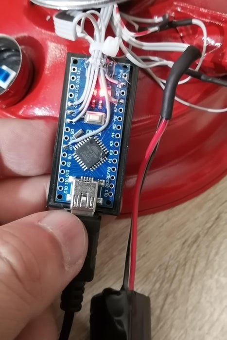
Glue the Arduino to their 3D printed case and lid.
Now is time to plug the Arduino into the computer and transfer the program lamp.ino
Put the battery and Arduino inside the oil tank.
Place the encoder cover in its place and solder it to the tank, as shown.
Step 12:
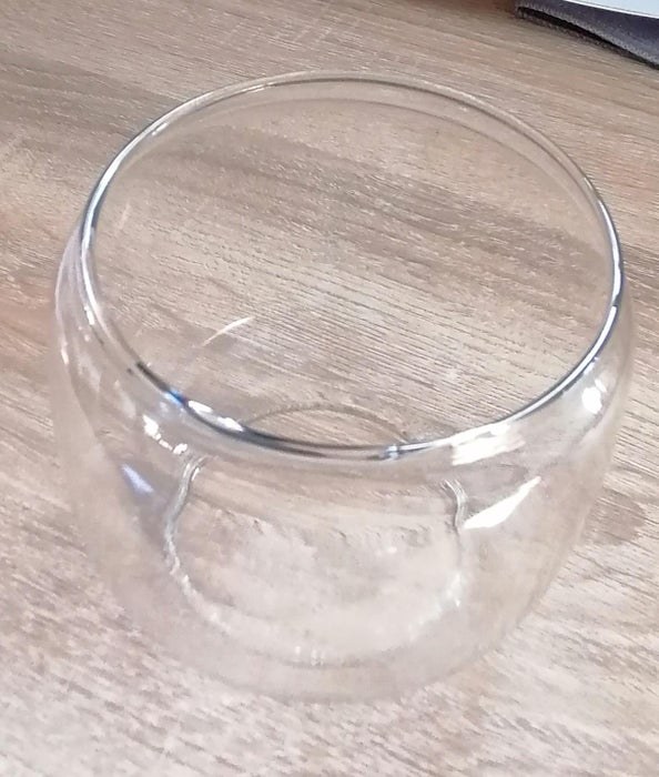
To give the frosted finish to the jar, you can use some spray paint, such as the Rust-Oleum one.
For that, cover the outside jar with paper and tape. Follow the spray’s instructions to paint the inner side of the jar.
Finally put back the jar in their place.
You can glue and paint a magnet in the tank to hold the cap.
Charge the battery by connecting a micro USB cable to a USB port.
Source: NeoPixel Ancient Oil Lamp