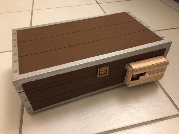
This instructable will explain how to wire, code, and build a functioning DIY arduino safe with multivibrator changeable 4-digit combination. Well what does that mean? A arduino safe with multivibrator changeable 4-digit combination is a functioning safe with a changeable password/combination, it features a series of multivibrator circuits to create the 4-digit combination, a input panel to enter in combination, open/closed detection using a magnetic switch, and more.
Supplies
Required Components:
- 1x RGB LED – Purchase Link
- 2x NE555 timers- Purchase Link
- 2x 0.1uf capacitor- Purchase Link
- 1xAND gate – Purchase Link
- 1x NOR gate – Purchase Link
- 4x LED – Purchase Link
- 7x pushbuttons – Purchase Link
- 1x Arduino – Purchase Link
- 5x 560 ohm resistors – Purchase Link
- 12x 10k ohm resistors – Purchase Link
- 1x Magnetic switch – Purchase Link
- 1x servo motor – Purchase Link
- 1x Dip Switch – Purchase Link
- 2x Mini breadboard – Purchase Link
- 1x Breadboard – Purchase Link
Other Items:
- Cardboard/wooden box
- popsicle sticks
- hotglue gun & hotglue sticks
- tape
- Wire strippers
- Drill and/or sciccors
- 9v battery
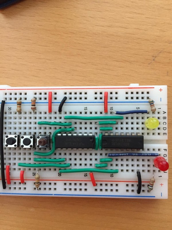
Step 1: Wiring 2x NE555 Timers
Materials Required for Step 1:
- 2x NE555 timers
- 2x 0.1uf capacitor
- 2x LED
- 4x pushbuttons
- 2x 560 ohm resistors
- 4x 10k ohm resistors
- 1x breadboard
Overview:
In this step you will wire the first two digits of your combination, each LED on the main breadboard represents a digit of the combination, if it’s on then that’s a 1, off is a 0. The two NE555 timer circuits act as the last two digits, the mode the timers are wired in is bistable mode, this allows the timer to act as a flip-flop circuit, flipping the LED from on to off using two push buttons. We are going to wire two of these circuits on the far left of the main breadboard.
In-Depth Steps:
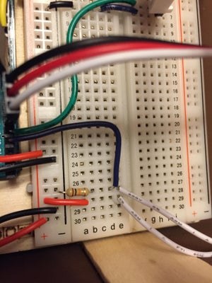
Start with the breadboard in front of you, then place your NE555 timer over the middle of the breadboard 2 slots on from the left, make sure the notch on the timer is facing to the right. Then connect pin 1 of the timer to the ground rail using a jumper wire and connect pin 8 of the timer to the power rail. Connect pin 5 & 6 to ground, connect pin 5 with a 0.1uf capacitor and connect pin 6 with a jumper wire. Connect pin 3 to a row on the breadboard left of the timer that is not connected to anything with an LED, then using a 560 ohm resistor connect the rail with the LED to ground. Next two slots to the right of the timer place two push buttons over the middle of the breadboard with one space in between them. Then connect the bottom right leg of each button to the power rail using 10k ohm resistors and the top left leg of each button to the ground rail using jumpers wires. Then connect the top right leg of one button to pin 2 on the timer and the top right leg of the other button to pin 4 on the timer. Then finally three spaces to the right place the second NE555 timer and repeat all the steps above.
Step 2: Wiring Gated SR Latch
Materials Required for Step 2:
- 1x AND gate
- 1x NOR gate
- 2x LED
- 3x pushbuttons
- 2x 560 ohm resistors
- 3x 10k ohm resistors
- build from previous step
Overview:
In this step you will wire the next two digits of the combination in the form of a gated SR latch, the reason it is gated rather than not is to avoid the “illegal” state of both inputs being 1, so this adds a third input, enable. This latch acts similar to the bistable mode NE555 timers in the terms of it is a flip flop circuit, but it flips between two LED”s instead of just one. Since the latch is gated you must hold the enable button to be able to use the other two buttons to switch between the two LED’s. This will be wired on the same breadboard used for the two NE555 timer circuits.
In-Depth Steps:
First take the breadboard from the last step, directly to the right of the furthest right pushbutton connect the two ground rails of the breadboard with a jumper wire, do the same for the power rail with a wire in between the two timer circuits. Next directly to the right of the wire connect the ground rails and place three push buttons over the middle of the breadboard with no spaces between them. for the first two buttons connect the bottom left legs to the power rail with jumper wires and the connect the top right legs to the ground rail with 10k ohm resistors. For the third button do the same but switch the placements connect the bottom left leg to ground and the top right to power. Next one place to the right of the last button place the AND gate (7408) over the center of the breadboard, make sure the notch on the chip is facing to the right. Then two places over place the NOR gate (7402) over the middle of the breadboard, ensure that the notch in the chip is facing to the left. Next complete the following connections between the two gates:
AND———NOR
pin6 ——> pin11
pin8 ——> pin3
NOR——–NOR
pin2 ——> pin13
pin1 ——> pin12
Next connect the bottom right pin of the furthest left push button for the latch to pin10 on the AND gate, then do the same for the next pin over but connect the leg to pin9 & pin4 on the AND gate. Finally connect the last button from the top right leg of the button to pin5 of the AND gate. Then place two LED’s to the right of the NOR gate one on the top and bottom, connect both short legs to the ground rails using 560 ohm resistors. Then finally connect the other leg of one LED to pin1 & for the other LED connect the other leg to pin3 of the NOR gate.
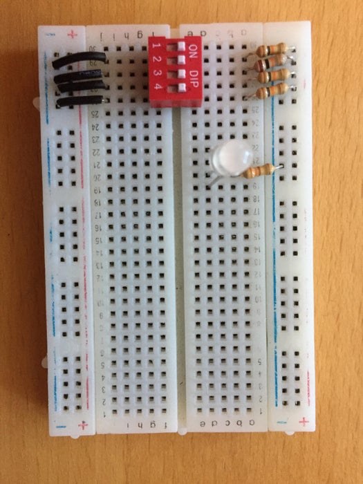
Step 3: Wiring Dip Switch & RGB LED
Materials Required for Step 3:
1x RGB LED
4x 10k ohm resistors
1x 560 ohm resistors
1x Dip Switch
1x Mini breadboard
Overview:
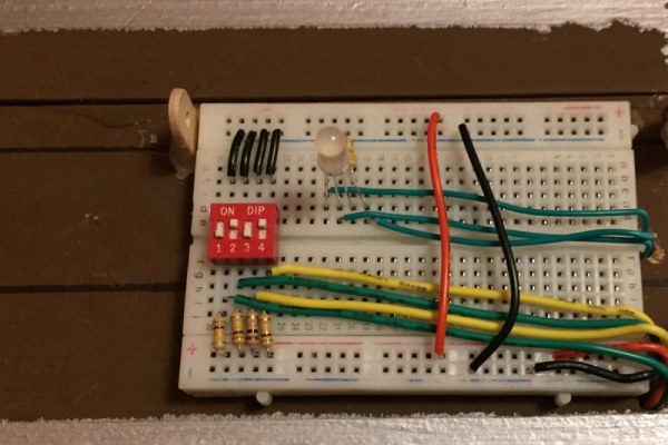
This section is where we will wire the dip switch and RGB LED which is the keypad section of the build. The dip switch is how the user inputs the 4-digit combination to open the safe and the RGB shows if the combination is correct/what state the safe is in. We will use one of the mini breadboards to wire the dip switch and RGB as it will be housed on the outside of the box in its own case.
In-Depth Steps:
First place the breadboard in front of you and place the dip switch over the middle of the mini breadboard one slot in from the left. Next on one side of the dip switch connect each leg individually to the power rail with 10k ohm resistors and on the other side connect each leg individually to the ground rail with jumper wires. Next to the right of the dip switch place your RGB LED in the breadboard and connect it to the power or ground rail with a 560 ohm resistor dependent if it is a common anode or cathode LED.
Step 4: Wiring Magnetic Switch & Servo Motor
Materials Required for Step 4:
1x 10k ohm resistor
1x Magnetic switch
1x Mini breadboard
1x Servo Motor
Overview:
This step is very simple, we are simply wiring the servo motor and magnetic switch, the servo motor is what drives the locking mechanism, it moves the rod back and forth allowing the box to open or not. The magnetic switch is used to detect when the box is open or closed so the user can only relock the safe when its closed.
In-Depth Steps:
On the left side of the mini breadboard connect the servo motor so each pin is in a different rail of the breadboard. Using jumper wires connect the ground cable, typically black or brown, to the ground rail and the power wire, typically red, to the power rail. Next place the magnetic switch in two slots in different rails on the right side of the breadboard connect one side to the power rail with a jumper wire and the other side to the ground rail with a 10k ohm resistor.
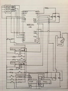
Step 5: Connecting Breadboards to Aurdino
Materials Required for Step 5:
- 1x Arduino
- 1x cardboard/wooden box
Overview:
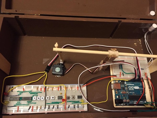
Now we have all the different sections of the build now to connect them all to the microcontroller so we can make this project one cohesive unit. If you will be integrating the circuits into an actual box to create the safe I would suggest placing the breadboards and arduino inside the box and then wire it. (make sure to leave room in the center of the box for the locking system.
In-Depth Steps:
Dip Switch & RGB:
First we will connect the RGB LED and the dip switch as these are placed on the outside of the box, first you will have to make a hole in the box with scissors or a drill close to where you will place your breadboard, this is how you will feed the wires through to the arduino inside the box. If you are not using a box you can simply just make the same connections outside the box. So first use jumper wires to connect individually each pin of the dip switch from the side with the resistors to one of these pins A0,A1,A2, and A3 on the arduino, the order does not matter as you can change the code to match the order you wired them in. Next connect the R, G, and B legs of the RGB LED to pin 11,10, and 9 on the breadboard, make sure each pin is only connected to one of the legs of the LED, each leg should not be connected to every pin.
Multivibrator Circuits:
Next is to connect the circuits used to set the 4 digit combination, first we can connect the two bistable mode NE555 timer circuits. To do this connect a jumper wire from pin3 of the NE555 timer and connect it to digital pin 13 on the arduino, do this for the second NE555 timer as well but connect it to digital pin 7 on the arduino. Next for the gated SR latch connect the short leg of the first LED (the one connected to ground by a resistor) to digital pin 6 on the arduino, do the same for the other LED but connect it to digital pin 5.
Magnetic Switch:
For the magnetic switch simply connect the cable that is running to ground using a resistor to digital pin 3 on the arduino using a jumper wire.
Servo Motor:
Finally connect the signal wire (white, orange or yellow) to digital pin 4 on the arduino using a jumper wire.
Ground/Power:
Finally connect the ground rails on all breadboards together using jumper wires, do the same with the power rails, then connect the 5v pin on the arduino to the power rail of the internal mini breadboard and the ground pin to the ground rail of the internal mini breadboard.
Step 6: Building Locking Mechanism
Materials Required for Step 6:
- Popsicle sticks/ thin plywood
- Wooden dowels(3 different sizes)
- Hot Glue gun & hot glue sticks
- Drill or scissors
Overview:
This is the system that the servo motor controls to actually lock the box it is housed in. The system is basically just sliding a dowel left and right to either block the lid from opening or not.
In-Depth Steps:
First hot glue popsicle stick or thin piece of wood to the inside wall of the box, have the wood be higher than the wall but short enough so the lid can still close. Then drill/cut a hole into the lid of the box going through the box and the center of the wood you just glued in to the box. Next take a piece of the larger sized dowel and cut a hole in the middle the size of the medium sized dowel to allow it to go through, next glue the piece of large dowel to two popsicle sticks to act as legs. Line up the hole in the dowel to the hole in the piece of wood glued to the side of the box and glue the legs of the dowel to the floor of the box. Now cut a piece of the medium sized dowel that is long enough to go through the large dowel and hole in the wood glued to the box. Then place the servo motor behind the legs of the dowel and glue it in place, now cut a shorter piece of the medium sized dowel that goes from the servo to the end of the dowel that is going through the dowel and lid of the box, and glue it to the servo motor end. The drill a hole in the back of the horizontal medium sized dowel and the top of the one glued to the servo so the holes line up then cut a piece of the smallest dowel and place it in the two holes you made, this acts as a hing so when the motor moves back the dowel glued to it it pulls back the one sitting horizontal.
Step 7: Building Input Pannel
Materials Required for Step 7:
- Popsicle sticks/ thin plywood
- Hot Glue gun & hot glue sticks
- Drill or scissors
- Wooden dowel
Overview:
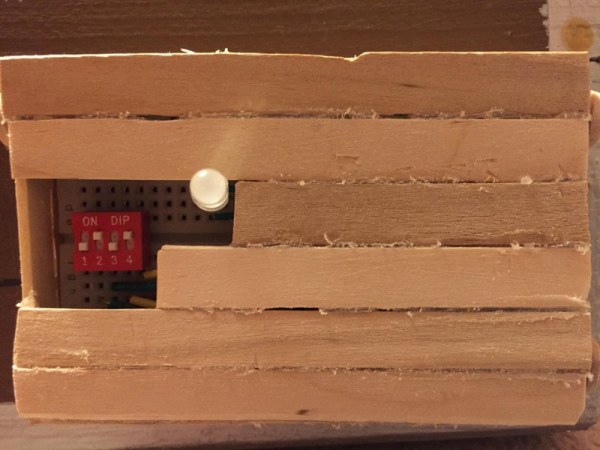
This part is very simple, we are just building a cover for the mini breadboard on the outside of the box with the dip switch and RGB LED. This is so it will look better and protect the components and cover up wiring.
In-Depth Steps:
First cut 4 popsicle sticks the length of the breadboard plus half an inch and then cut four popsicle sticks the width of the breadboard. Glue these together creating a rectangle two popsicle sticks high, then cover the top in popsicle sticks cutting out space so the RGB LED and dip switch are still visible. Then drill a hole in three corners of the breadboard cover you just made the size of your wooden dowel, then drill three holes in three different popsicles sticks the same size. Next cut down the popsicle sticks so the holes match up with the ones in the cover and the sticks are long enough just to go past the height of the cover, Next glue the popsicle sticks with the holes in onto the front of the box so the cover can fit between them, ensure the placement will cover the hole where the wires are fed through. Next cut dowels and insert them into the holes so it holds the cover & breadboard on the front of the box.
Step 8: Writing Code
Now all the hardware and construction is all done and dusted we can finally add the code and the project is complete. The code can be found on the attached file or you can copy and paste it from below. The way it works is it starts by initializing all the variables and setting the pins, but in the setup it also has a start up sequence. It waits and flashes the RGB blue and green until the magnetic switch id reads as high by closing the box, it then locks itself and is ready to go. Then it constantly reads the set pins and input pins and sets the rGB LED red until all the pins match their respect pairs. Once this happens the LED flashes green and blue and the servo opens the lock and the box is now open. Then finally to lock the box again you must close the box setting the magnetic switch high and then set all the dip switch pins high and then the box will lock and the LED will turn RED once again. This loops and loops until reset or unplugged.
Code:
#include
int red;
int green;
int blue;
int redpin = 9;
int greenpin = 11;
int bluepin = 10;
int Mswitch = 3;
int inpin[4] = {A2,A0,A1,A3};
int setpin[4] = {5,6,7,13};
int CSpin[4];
int CIpin[4];
int O_C; Servo lock;
void setup() {
lock.attach(4);
pinMode(13, INPUT);
pinMode(11, OUTPUT);
pinMode(10, OUTPUT);
pinMode(9, OUTPUT);
pinMode(7, INPUT);
pinMode(6, INPUT);
pinMode(5, INPUT);
pinMode(3, INPUT);
pinMode(A0, INPUT);
pinMode(A1, INPUT);
pinMode(A2, INPUT);
pinMode(A3, INPUT);
lock.write(90);
while(true){
O_C = digitalRead(Mswitch);
if(O_C == HIGH){
delay(2000);
lock.write(80);
break;
}else{
color(0,255,0);
delay(1000);
color(0,0,255);
delay(1000);
}
}
}
void color(int red,int green,int blue) {
analogWrite(redpin, red);
analogWrite(greenpin, green);
analogWrite(bluepin, blue);
red = 255 – red;
green = 255 – green;
blue = 255 – blue;
}
void loop() {
for(int i = 0; i <= 3; i++){
CSpin[i] = digitalRead(setpin[i]);
CIpin[i] = digitalRead(inpin[i]);
}
O_C = digitalRead(Mswitch);
if(CSpin[0] == CIpin[0] && CSpin[1] == CIpin[1] && CSpin[2] == CIpin[2] && CSpin[3] == CIpin[3] && O_C == HIGH){
color(0,255,0);
lock.write(90);
while(true){
O_C = digitalRead(Mswitch);
for(int w = 0; w <= 3; w++){
CIpin[w] = digitalRead(inpin[w]);
}
if(O_C == HIGH && CIpin[0] == HIGH && CIpin[1] == HIGH && CIpin[2] == HIGH && CIpin[3] == HIGH){
lock.write(80);
color(255,0,0);
break;
}else{
color(0,255,0);
delay(1000);
color(0,0,255);
delay(1000);
}
}
}else{
color(255,0,0);
}
}
Source: Arduino Safe With Multivibrator Changeable 4-digit Combination