Summary of Analog Write with 12 LEDs on an Arduino Mega
This project demonstrates fading 12 LEDs sequentially on an Arduino Mega board using analogWrite. The code employs nested loops to incrementally increase and decrease brightness, creating a smooth wave effect. Each LED is connected through a current-limiting resistor to control current flow safely.
Parts used in the 12 LED Fade Project:
- Arduino Mega Board
- 12 LEDs
- 12 220 ohm resistors
- Hook up wire
- Breadboard
This example fades 12 LEDs up and the down, one by one, on an Arduino Mega board.
Circuit
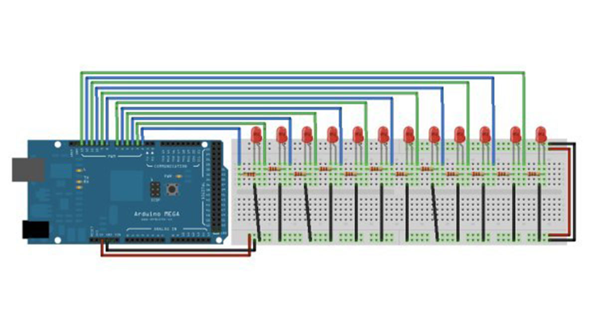
image developed using Fritzing. For more circuit examples, see the Fritzing project page
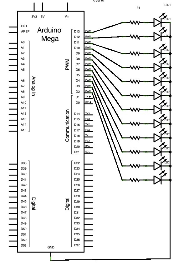
Connect the longer, positive legs of (anodes) 12 LEDs to digital pins 2-13 through 220 ohm current limiting resistors. Connect the shorter, negative legs (cathodes) to ground.
Schematic
Code
In the setup() function of the code below, a for() loop is used to assign digital pins 2-13 of the Mega as outputs.
Next, in the loop() function of the program below, a trio of nested for() loops are used.
The first of these loops,
moves through each of the LEDS one by one, from the lowest pin to the highest. Before this loop is allowed to move from one pin to the next, two things must be accomplished. First, you brighten the individual LED through these lines of code:
analogWrite(thisPin, brightness);
delay(2);
}
Hardware Required
- Arduino Mega Board
- (12) LEDs
- (12) 220 ohm resistors
- hook up wire
- breadboard
- How many LEDs are used in this project?
The project uses 12 LEDs. - What type of board is required for this circuit?
An Arduino Mega board is required. - Does the code use digital or analog pins?
The code assigns digital pins 2-13 as outputs. - What is the purpose of the 220 ohm resistors?
The resistors act as current limiting resistors for the LEDs. - Can I connect the LED cathodes directly to power?
No, the shorter negative legs (cathodes) must be connected to ground. - How does the code change the brightness of the LEDs?
The code uses analogWrite with a loop that increments brightness from 0 to 255. - What tool was used to develop the circuit diagram?
Fritzing was used to develop the circuit image. - Are hook up wires necessary for this setup?
Yes, hook up wire is listed as a major component.