Summary of NeoMatrix 8×8 Word Clock
This project builds a colorful 8x8 NeoPixel word clock using an Adafruit NeoPixel NeoMatrix, a Pro Trinket 5V microcontroller, and a DS1307 RTC breakout in a laser-cut acrylic enclosure. It displays time in five-minute increments, is USB powered, and retains time via the DS1307 when unplugged. Assembly covers soldering the RTC headers, stacking it on the Trinket, wiring the NeoMatrix, installing the matrix and Trinket into the acrylic case, adding a pixel guard and diffuser, and uploading the code via the Trinket bootloader.
Parts used in the Word Clock:
- Pro Trinket 5V
- DS1307 Real Time Clock breakout board kit
- NeoPixel NeoMatrix 8x8
- Wordclock laser-cut acrylic enclosure
- 4-40 black nylon screws (x14)
- 4-40 black nylon nuts (x14)
- 2-56 black SS machine screws (x2)
- 2-56 Black SS Hex Nut (x4)
- Wires (~22-26 AWG, silicone cover recommended)
- MicroUSB cable
- 5V 1A USB port power supply (optional)
Are you fascinated with the passage of time? Do you want a stylish, modern and functional timepiece to add to your clock collection? The word clock is a one-of-a-kind time telling device, using a grid of letters to spell out the time. While you could spend thousands of dollars on other versions of this idea, this project is an inexpensive and quick way to build one for yourself.
The word clock uses the Adafruit NeoPixel NeoMatrix 8×8 to create a colorful word clock! As such, it features an original 8×8 layout of letters in order to form all of the different time phrases. You can power it over USB so it makes for a great desk time-keeper. This clock also uses the DS1307 Real Time Clock breakout kit so it’ll keep time even while unplugged! The DS1307 has an accuracy of +/- 2 seconds per day, and the clock tells the time with a precision of five minutes. The microcontroller board we’re using is the Pro Trinket 5V but you can swap it with any Arduino compatible or microcontroller that can use I2C and NeoPixels.
Step 1: Parts List
Parts
- Trinket Pro 5V
- DS1307 Real Time Clock breakout board kit
- NeoPixel NeoMatrix 8×8
- Wordclock laser-cut acrylic enclosure
- 4-40 black nylon screws (x14)
- 4-40 black nylon nuts (x14)
- 2-56 black SS machine screws (x2)
- 2-56 Black SS Hex Nut (x4)
- Wires, silicone cover are easiest to use but just about any ~22-26 AWG wires will do
- MicroUSB cable (for uploading the code and powering the clock)
- 5V 1A USB port power supply (if you don’t want to just power the clock from your computer)
Tools
- A computer which can program the Trinket Pro 5V
- Soldering iron
- Solder
- Wire strippers
- Diagonal cutters
- Small flathead screwdriver (2.4mm)
Step 2: Circuit Assembly
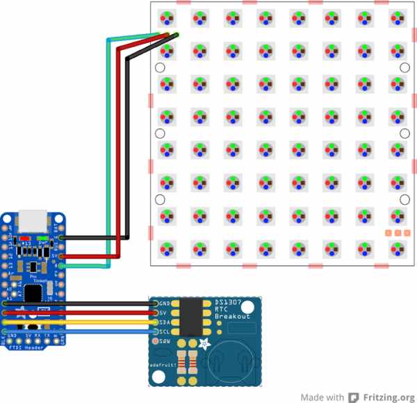
Start by assembling the DS1307 Real Time Clock breakout board by following this learn guide. You only need to solder in the male headers for GND, 5V, SDA and SCL. You can leave off SQW since it isn’t used and the header won’t fit nicely on top of the Pro Trinket. If you do solder it in, you can clip the bottom lead off.
Once the DS1307 breakout is assembled with headers, you can solder it on top of the Trinket Pro 5V so that the DS1307 GND lines up with the Pro Trinket A2, 5V with A3, SDA with A4 and SCL with A5. Make sure the boards are lined up correctly! SDA and SCL need to be connected to A4 and A5, respectively.
Connect the NeoMatrix GND to the Trinket Pro GND, 5V to 5V and DIN to Pin 8. Cut the wires 5-8 inches or 13-20 centimeters long. Solder the wires into the back of the NeoMatrix so that the wires won’t be visible from the front.
Step 3: Attach Circuit
Now that your circuit is complete, it’s time to start attaching it to the laser cut enclosure. You’ll need to find a laser-cutting shop, hacker space or other friend with a laser cutter to cut out the pieces. You can find the files to cut in this github repository, use 1/8″ clear and black acrylic – or get creative and do something else!
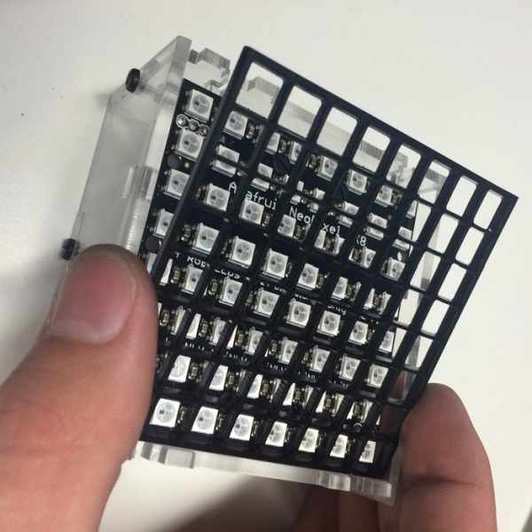
Start by attaching the neopixel matrix to the acrylic plate that will hold it in place within the enclosure.
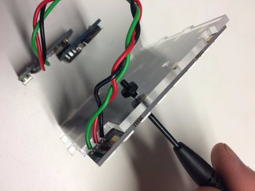
Now take the back panel and attach the stainless steel machine screws which will hold the Pro Trinket in place. Attach the Pro Trinket to the back plate, making sure the screws are tightened down firmly.
Connect the neopixel matrix to the back plate with the side panel, being careful to use the panel with the hole for the micro USB.
Now you can add the other side panel and the top and bottom pieces, attaching each with the black nylon screws as you go.
Once all the clear acrylic pieces are put together, you are ready to add the pixel guard and diffuser.
Step 4: Assemble Enclosure
Put the pixel guard in place on top of the neopixel grid. This will help contain the light from each pixel, making each letter on your clock crisper and easier to read.
Diffusers are used to spread out the light from the neopixels and make the text on the faceplate easier to read. You can make a diffuser from a plain sheet of paper, or any other material that will even out the bright light from the neopixels. Just trace the outline of the neopixel matrix and cut it out.
Place the diffuser on top of the neopixel matrix. Now you are ready to attach the faceplate. Before putting the faceplate in place, pull the protective paper cover off the faceplate. Any letter pieces should get pulled out along with the paper. Use tweezers to poke out any bits of letters that don’t fall out when the paper is pulled off.
Step 5: Upload the Code
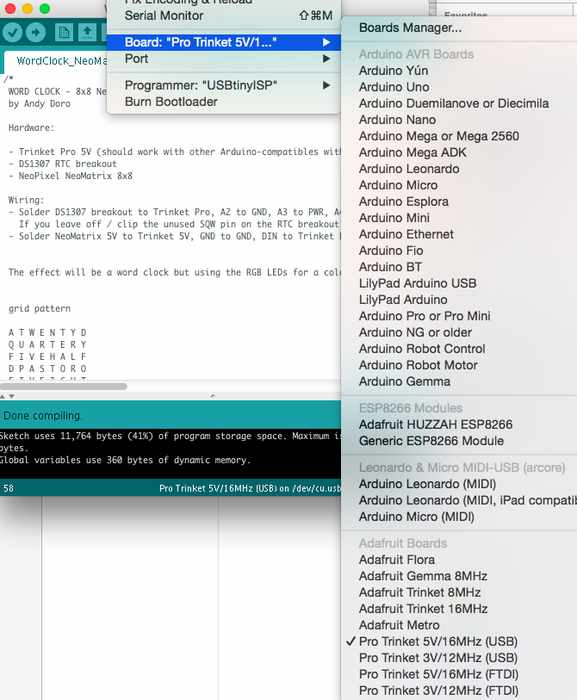
Put the Pro Trinket into bootloader mode either by unplugging and replugging the Pro Trinket into the computer with your MicroUSB cable or by hitting the reset button. The reset button can be difficult or impossible to access if you’ve soldered the RTC on top or if you’ve already installed the circuit into the enclosure! So I find plugging the board into USB to work best.
When the red LED on the Pro Trinket is pulsing, the board is in bootloader mode. Once you’re in bootloader mode, upload the code! If everything was done correctly, it should start telling you the time!
Source: NeoMatrix 8×8 Word Clock
- What microcontroller is used in the project?
The project uses a Pro Trinket 5V microcontroller. - Can the clock keep time when unplugged?
Yes, it uses the DS1307 RTC breakout which keeps time while unplugged. - How accurate is the DS1307 RTC?
The DS1307 has an accuracy of +/- 2 seconds per day as stated in the article. - What NeoPixel hardware is used for the display?
An Adafruit NeoPixel NeoMatrix 8x8 is used to create the word clock display. - How precise is the clock when telling time?
The clock tells time with a precision of five minutes according to the article. - Which pins must SDA and SCL be connected to on the Pro Trinket?
SDA must be connected to A4 and SCL to A5 on the Pro Trinket. - Where should the NeoMatrix data input (DIN) be connected?
DIN should be connected to Pin 8 on the Pro Trinket. - What materials are suggested for the diffuser?
You can make a diffuser from a plain sheet of paper or any material that evens out the NeoPixel light. - How do you put the Pro Trinket into bootloader mode?
Unplug and replug the Pro Trinket into USB or press the reset button; the red LED pulsing indicates bootloader mode. - Are assembly files for the laser-cut enclosure provided?
Yes, the article states the cutting files are available in the referenced GitHub repository.