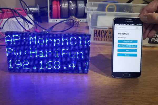
Summary of Morphing Digital Clock
This project builds a WiFi-connected P3 64x32 RGB LED matrix clock using an ESP8266 NodeMCU. No soldering or programming skills required; code is provided and timezone setting was later added. The guide covers parts, wiring the ESP pins D0–D8 and GND to the matrix, connecting left/right matrix connectors, and power requirements and cable notes. Double-check connections before powering up.
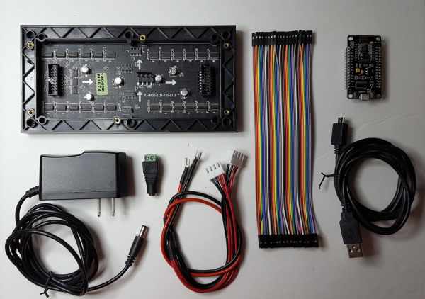
Parts used in the Morphing Digital Clock:
- P3 64x32 RGB LED Matrix
- NodeMCU 32MB ESP8266 WiFi Microcontroller module
- Female to Female 20cm Dupont jumper wires
- Micro USB Data/Sync cable
- 5V phone charger wall adapter (USB)
- 5V 2A minimum Power Supply
- Solderless Female barrel connector (for display power cable)
A quick video about this project. I have since implemented a way to set timezone.
Thanks to the work of the Arduino and ESP8266 community, this cool clock is a surprisingly easy to build!
- Just two main components: Display (obviously) and a WiFi MicroController
- No soldering required
- No programming skill required, code is provided!
Let’s get started!
Step 1: Parts List
Although I’ve included links to where I bought my parts, these parts can be easily purchased from other vendors all around the world.
- P3 64×32 RGB LED Matrix $20
- NodeMCU 32MB ESP8266 WiFi Microcontroller module $4.95
- Female to Female 20cm Dupont jumper wires $0.85
- Micro USB Data/Sync cable and 5V phone charger wall adapter (I had these and didn’t have to buy it)
- 5V 2A MINIMUM Power Supply (I had this and didn’t have to buy it) $7.95
- Solderless Female barrel connector to connect the Power Supply to the display power cable.
IMPORTANT:
- Some USB cables are designed just for power delivery (charging) — these are ok to power the finished clock, but to upload code to the ESP we will need a data/sync USB cable.
- The P3 RGB Matrix has over 6000 LEDs. For this clock, we will never turn all of them at once, so 2 Amp is more than sufficient. However, if you plan on doing more with the display and have all LEDs set to white, the recommended power supply is 8 Amp minimum.
Step 2: Wiring Summary
There are a lot of wires, but don’t worry. All we’re doing is connecting one pin to another.
Just take your time. Double check each connection before and after you plug it in.
Make sure the wires are fully inserted so they would not accidentally come undone. They are quite snug when fully inserted.
Step 3: ESP Wiring
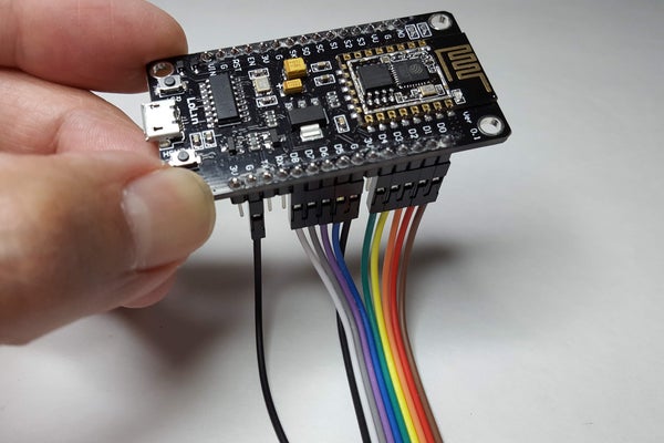
First, let’s put jumper wires on the ESP. Don’t worry if your wire colors are different than mine. Which pair of pins are connected by each wire is what is important.
Do NOT connect the ESP to your PC YET. We need to complete all wiring before we power anything up.
We are using pins D0 through D8 and two GND.
We can skip the 3V pin because the ESP will be powered via the USB port.
We also skip the Transmit and Receive pins because we will communicate to the ESP via USB or WiFi.
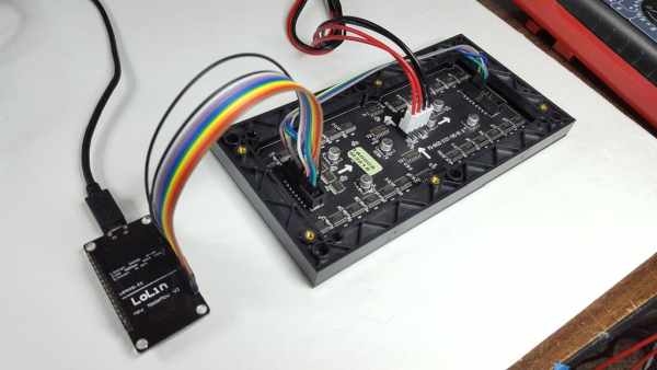
Step 4: Matrix Wiring Part 1

Next, take the other end of the jumper wires we’ve just hooked up to the ESP and plug them into the matrix.
Again, the chart includes the colors of the wires that I used, but of course your colors might be different.
What is important is that you connect the ESP pins to the matrix as shown in the table.
The matrix is NOT symmetrical, there is a left/right, up/down. Please note the white arrows.
Connectors on my matrix are not labeled, so I’ve added a photo with labels. Your matrix might be slightly different. These resources discuss other board versions in great detail:
- PxMatrix by Dominic Buchstaller
- RGB Led Matrix With an ESP8266 by Brian Lough aka WitnessMeNow
Step 5: Matrix Wiring Part 2
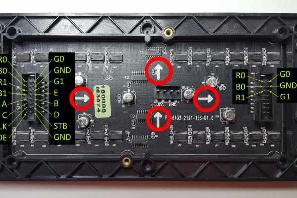
Second set of jumper wires connect the left connector to the right connector of the matrix.
Third photo shows the right side of the matrix.
Source: Morphing Digital Clock
- Do I need to solder for this project?
No, no soldering is required according to the article. - Do I need programming skills to build this clock?
No programming skill is required; the code is provided. - What type of USB cable is needed to upload code to the ESP8266?
A data/sync USB cable is required to upload code; charging-only cables will not suffice. - Which ESP8266 pins are used to connect to the matrix?
The project uses pins D0 through D8 and two GND connections on the ESP. - Can the ESP8266 be powered from the 3V pin?
No, the 3V pin is skipped; the ESP is powered via the USB port. - What minimum power supply is recommended for this clock?
A 5V 2A minimum power supply is recommended for this clock setup. - What power supply is suggested if all LEDs are driven white?
If all LEDs are set to white or used extensively, an 8A minimum power supply is recommended. - Should I connect the ESP to my PC before completing wiring?
No, do not connect the ESP to your PC until all wiring is completed. - Does the matrix have a specific orientation when wiring?
Yes, the matrix is not symmetrical and has a left/right and up/down orientation; follow the arrows and connector labeling.