Summary of Necomimi Arduino Cat Ears
This article details a DIY project to build "Necomimi" cat ears using an Arduino Uno and an ADXL345 accelerometer. The creator replaces expensive brainwave sensors with head-tilt detection via the accelerometer to control two servos, which move the ears. The project serves as an Arduino primer, covering component sourcing, soldering, and basic programming to create a wearable prototype for cosplay or fun.
Parts used in the Necomimi Cat Ears:
- Arduino Uno
- ADXL345 accelerometer breakout board
- Two standard servos
- Protoboard or breadboard
- Wire (stripped)
- LEDs and resistors (200-300 ohm)
- Soldering station and tools
- Power packs for Arduino and servos
- Craft fur
- Craft sheet foam
- Ear lining material
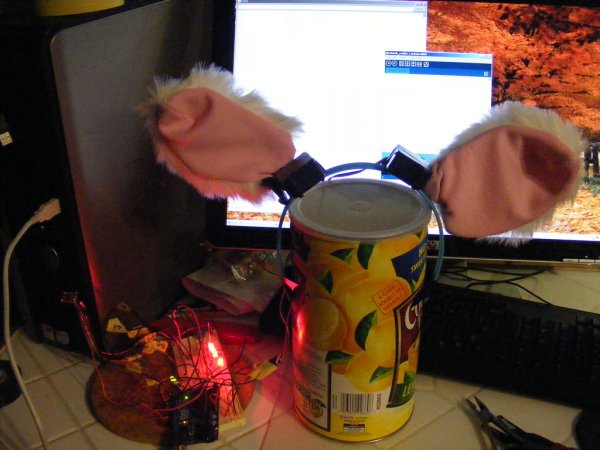
They are so dang cute. If you have ever seen the cool promo for the Necomimi Neurowear wearable set of cat ears that respond to brainwaves, you would want a set too. But it seems they may be vaporware since it hasn’t materialized on the market yet, not that I would be able to afford them though. Necomimi or nekomimi is Japanese for “cat ears”.
What do you do with them? You can wear it for Halloween or everyday, if desired. It may be for the anime otaku seriously into their cosplay. For the furries out there, I’m not asking so don’t tell me.
Now what would the simplified caitlinsdad version be? Well, getting into advanced monitoring and feedback of brainwaves might be kinda expensive(they are dumping at the toy mega-store those Star Wars force trainers – control the floating ball with your mind- now $60 from $100 or maybe gut an i-dog but then I don’t think the gears are powerful enough) and building some raw circutry is way more than I want to do. Pulley and invisible strings is so ghetto(Not that there’s anything wrong with that…). A joystick that controls some motors on a headband? I know, how about servos controlled by an Arduino? And how about using an accelerometer to determine tilt/movement/position of the head to trigger ear movement. Tilt sensor switches might be too basic. GPS gets complicated and compass magnetomometer only points North.
This gives me a project to use with my recently acquired Arduino(no, it did not fall off a truck…I have a receipt). Besides, Caitlin says I have to make this or sew her a custom sling/messenger book bag.
This instructable may be more of an Arduino primer than about the cat ears. Note that this is a prototype project and I am throwing it out at this stage in the spirit of Open Source. I know it can be improved a lot by others and with more time to tweak it.
Okay, they look like bunneh ears, kinda like a cat.
Step 1: Getting started with Arduino
I found that my local computer supergeekstore had stocked Sparkfun retail Arduino components. Maker Faire sells them at the Make: Shed. Adafruit has them also. You could get them from Sparkfun themselves. Hmmm, tax works out about what I would pay in shipping and would not have to wait at the door for the package. I had bought an Arduino Uno $30(other variants($25) require the FTDI programmer USB interface($15) which is built in to the Uno). Other add-ons can run up the tab. I have a 2×16 LCD display($20) to play with next. See if the kits will save you any money. The books were all text-book priced and I was sure info could be gleaned from the internet.
You have to go to arduino.cc to download the Arduino programming interface for your PC. It allows you to create “sketches” or programs that get uploaded to the ATmega microprocessor chip on the Arduino board. The site contains tutorials and examples of code used to implement the devices you want to interface with the Arduino.
On a PC, only thing tricky in getting started is you have to manually install the USB drivers so that it recognizes the Arduino on a COM port.
A computer with the Arduino software installed, USB drivers, a USB cable to connect the PC and Arduino, and the Arduino Uno is all you need to get started. The Uno has an LED onboard that you can control with a sketch.
I wanted to get an Arduino so I could do some of those cool things like build 3-D LED matrices and light reactive tabletops.
It is easy to get your LED blinking and fading. It was easy to modify an example sketch to do Cylon lights(Knight Rider lights), just add more LEDs and resistors. Read up on all the LED instructables and you can throw around terms like “charlieplexing”.
So, always hook up an LED with a resistor so you don’t burn it out(search “LED calculator” for widgets to find the right resistor value). A trip to Radio Snacks to get a bag of assorted LEDs and 100 ohm resistors. A trip back to get a protoboard and 100 ohm resistors because I failed to note 100k resistors are not 100 ohm resistors. And another trip back after realizing I do not have any wire thin enough (22 gauge?) that fit in the holes on the protoboard (and get solid not stranded).
I saw a precut pack of jumpers but hey, I have a nice pair of wire strippers and can do that. I saw online some premade jumpers that had a patch-cord plug-like cover on the ends of the wires. Hey, I could get some tiny plastic jewelry beads, and pass the wire through and maybe solder or tin the ends of the wire to keep it in place. Do not do that, tinning the ends makes it not fit in the holes. Find a bead that fits snugly or put a drop of glue to hold it in place.
Back to this project:
Once you are comfortable enough to wire up your protoboard and have done a few sketches, you should be able to tackle this project.
You will need to get:
* Protoboard or breadboard to wire the circuit together.
* Wire, lotsa wire with the ends stripped
* 2 standard servos (My brother flies radio-controlled jets and helicopters so he had some spares to give me. Free is always good)
three wire, 6 volts DC in, pulse-width-modulation PWM signal
* ADXL345 accelerometer breakout board – $30
* some LEDs and appropriate resistors (200-300 ohm usually works for your standard red/green/yellow medium sized 5mm LED)
The LEDs are really just diagnostic LEDs and indicators to help you fine tune your programming.
* You will need some basic soldering skills and tools.
* Power pack for your Arduino and power pack for your servos to make it portable
* Some craft fur, craft sheet foam and ear lining material
* Basic sewing skill. You can sew this by hand, machine or just use tape, glue/iron-on interfacing.
Step 2: ADXL345 Accelerometer Breakout Board
I had purchased 2 accelerometer boards at the store. 1. I knew I would be making two sets of necomimi. 2. Always have a backup. 3. When you experiment, prepare to toast one of your components. So I also got another Uno to back up the one I already had.
This breakout board(you can buy just the chip and figure out how to do that surface mount soldering which is really tricky) has the chip mounted with some other critical capacitors/resistors on a circuit board ready for you to wire up. Man, is this breakout board tiny.
At The Shack, I got their digitally controlled soldering station on sale for $50 and this was the first time I got to fire it up.
Everything was connected and powered up. I had forgot there was a clear plastic shipping tube on the soldering tip and I had just put it back into the soldering station holder well. So I had to spend some time scraping off the melted plastic and gunk off the tip. Minor setback.
I decided to hardwire 8 jumper wires to the breakout board so I could plug the leads into my protoboard.
No instructions come with this board so I took a good guess on how to solder the leads in. If they surface mount on one side then I would plug the wires in on the bottom side. The pads were not pretinned and did not have a copper surface so I couldn’t tell which would be better to solder on.
Did I mention how small this breakout board is?
I used the first preset temperature setting on the soldering station figuring, I am working with sensitive electronics, too much heat is bad…
It was kinda hard to melt the solder but I got one wire in. Crank up the next higher setting. Solder still doesn’t melt on contact but seems to work.
For more detail: Necomimi Arduino Cat Ears
- What is the simplified version of the commercial Necomimi?
The simplified version uses an Arduino and an accelerometer to detect head tilt rather than expensive brainwave monitoring. - Can I use raw circuitry instead of a breakout board?
The author notes that building raw circuitry is too complex for this project, so they used a pre-made breakout board. - How do you power the servos and Arduino for portability?
You need separate power packs for your Arduino and your servos to make the device portable. - What resistor value works for standard 5mm LEDs?
A resistance of 200-300 ohms usually works for standard red, green, or yellow medium-sized 5mm LEDs. - Where can I buy Arduino components?
Components are available at local computer stores, Sparkfun, Maker Faire, Adafruit, or directly from Sparkfun. - Do I need special USB drivers for the Arduino Uno?
Yes, you must manually install the USB drivers on your PC so it recognizes the Arduino on a COM port. - Why did the author buy multiple accelerometer boards?
The author bought extras to have backups for making two sets of ears and because components might get damaged during experimentation. - What is the function of the diagnostic LEDs in this project?
The LEDs serve as indicators to help fine-tune the programming and monitor the system status.