The purpose of this Instructable is to build a portable device that can measure the speed of sound in refrigerant gases and use this data to identify them.
The speed of sound in an ideal gas is related to two characteristics of the gaseous substance, its molecular mass (kg/mol) and its adiabatic constant (heat capacity ratio), or its average values in case of being a mixture of gases.
It is for this reason that the measurement of the speed of sound can be used as a preliminary way to identify a pure gas or mixture of gaseous substances.
The measurement can be performed using an ultrasonic proximity sensor, to measure the round trip time ( t/2 ) of a sonic pulse in a plastic tube of known length ( x ) (echo method), filled with the gas under study ( v = 2x/t ).
Since the speed of sound is also absolute temperature dependent, it must be measured using a digital temperature sensor.
The values measured by the sensors are captured and processed by an Arduino microcontroller that transmits them via bluetooth to a mobile application, designed with App Inventor 2, which will allow to calibrate the length of the plastic tube using a reference gas whose sound speed is known.
The application will use this information to calculate the sound speed of an unknown sample of a refrigerant gas and perform preliminary identification (see disclaimer **).
Supplies
- PVC pipe piece approximately 14 cm long and 4.8 cm in external diameter (1-1/2”).
- 2 PVC pipe caps approximately 4.8 cm in internal diameter (1-1/2”).
- 2 Toothpaste tube shoulder pressure caps.
- 1 Piece of leak repair tape about 15 cm x 25 cm.
- Epoxy glue.
- 1 Plastic container.
- 1 Breadbord.
- 1 Arduino Nano V3.0 CH340 with mini usb cable.
- 1 HC-SR04 ultrasonic sensor.
- 1 TMP36 digital temperature sensor.
- 1 Bluetooth HC-06.
- 1 1k ohm resistance.
- 1 2k ohm resistance,
- Male/male jumpers cable.
- Male/Female jumpers cable.
- 1 Male/female usb cable.
- 1 Portable battery charger (6000 mAh 3.7V, Out 5V, Output Max. 2.4A)
- Electric tape.
- Velcro tape.
Step 1: Measuring Probe
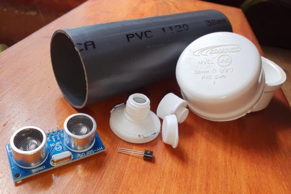
The measuring probe is basically a piece of PVC pipe approximately 14 cm long by 4.8 cm external diameter (1-1/2”) to which three holes are drilled, two for gas inlet and outlet (provided with pressure caps of the type used in toothpaste tubes) and another for inserting a digital thermometer.
This pipe will be closed at its ends by two PVC pipe caps approximately 4.8 cm internal diameter (1-1/2”). One of the caps will have two perforations to accommodate the emitter and detector of the ultrasonic sensor. This part of the device is going to be the point of emission and detection of ultrasonic pulses, while the flat face of the other cap, opposite the emission point will be the rebound point (echo) of the pulses.
The following is the procedure for constructing the measuring probe:
- From a 1-1/2” PVC pipe cut a piece about 14 cm long.
- About 4 cm from each end of the tube piece make two perforations, in opposite directions, approximately 5 mm in diameter.
- On the perforations made paste with epoxy resin the two pressure caps of toothpaste tubes.
- Halfway through the tube and perpendicular to the plane formed by the two holes described above open a hole about 1 cm in diameter.
- Through the above hole insert the temperature sensor TMP36, attached to its connecting cables and with the help of electrical tape stick to the upper inner wall of the PVC tube leaving exposed the sensor head. Fix externally with epoxy glue.
- Make two perforations approximately 1.5 cm in diameter separated by 2.5 cm to one of the PVC pipe caps so that they adjust the emitter and receiver of the ultrasonic sensor HC-SR04 and that are centered on the face of the cap. Fix the HC-SR04 sensor with expoxi glue making sure to seal all slots. Let the glue dry.
- Place the cap with the ultrasonic sensor and the cap that will function as a rebound surface, at the ends of the tube (measurement probe). Coat the rest of the exposed externas surface of the tube with leak repair tape so that it is thermally insulated.
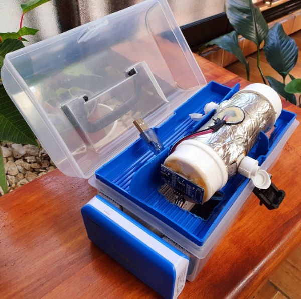
- Attach the measuring probe to the plastic container which, depending on the specific container you have, will require making cuts to adjust it.
- Make connections of the ultrasonic sensor and temperature sensor to the Arduino processor as indicated in the next section.
Step 2: Arduino Connections and Code
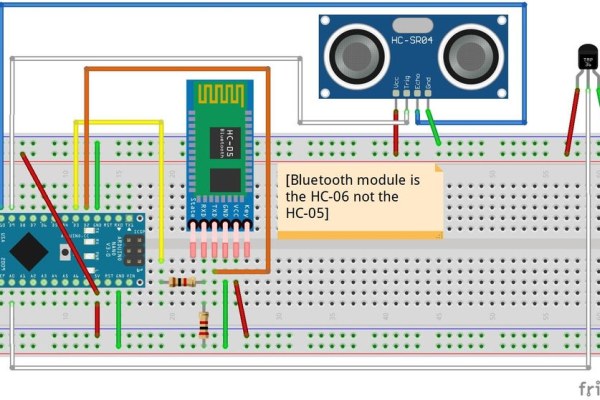
The connections of the measuring probe to the Arduino controller are shown in a Fritzing scheme that is attached (SoundSpeed_2021.fzz). The scheme is clear only because the Bluetooth emitter version is the HC-06 and not the HC-05 indicated in the diagram (this version does not appear in Fritzing components). It should also be noted that while the HC-06 Bluetooth component can operate with input voltages between 3.3 and 5 volts the higher value was chosen, otherwise the signal is frequently cut off.
Attached is the programming code of the Arduino Nano V3.0 CH340 (SoundSpeed_BT_2021.ino) in which two important points should be noted.
The first is that the float constant CorrecTemp -4 is a correction that is made to the initial measurement of the temperature sensor. This correction is estimated by reading the temperature value that the sensor marks when immersed in an ice bath (ice floating in water). The deviation of 0°C, which is the value that the ice bath should have, is the one used as a temperature sensor correction.
The other point is delay(950) value which must be less than or equal to the bluetooth clock speed in the App Inventor 2 app.
The code was uploaded to the Arduino Nano using the IDE1.8.5 and a Portable battery charger (6000 mAh 3.7V, Out 5V, Output Max. 2.4A) was used as a power supply (attached to the plastic container using Velcro tapes).
// SouundSpeed_BT_2021<br>// IDE 1.8.5
// Adapted and modified by Alberto Villalobos (IDE 1.8.5)
//
// Basic Bluetooth sketch HC-06_01
// Connect the HC-06 module and communicate using the serial monitor
// The HC-06 defaults to AT mode when first powered on.
// The default baud rate is 9600
// The HC-06 requires all AT commands to be in uppercase. NL+CR should not be added to the command string
//
// Ultrasonic Sensor HC-SR04 and Arduino Tutorial
// Crated by Dejan Nedelkovski,
// <a href="http://www.HowToMechatronics.com">  <a href="http://www.HowToMechatronics.com" rel="nofollow"> <a href="http://www.HowToMechatronics.com" rel="nofollow"> www.HowToMechatronics.com></a>>></a>>
#include <softwareserial.h>
SoftwareSerial BTserial(2, 3); // RX | TX
// Connect the HC-06 TX to the Arduino RX on pin 2.
// Connect the HC-06 RX to the Arduino TX on pin 3 through a voltage divider.</softwareserial.h>
float duration;
// defines pins numbers
const int trigPin = 9;
const int echoPin = 10;
//TMP36 Pin Variables
int sensorPin = 0; //the analog pin the TMP36's Vout (sense) pin is connected to
                   //the resolution is 10 mV / degree centigrade with a
                   //500 mV offset to allow for negative temperatures
float Temperatura;
float CorrecTemp = -4; //Corrección a la temperatura medida inicialmente por el sensor

void setup() {

pinMode(trigPin, OUTPUT); // Sets the trigPin as an Output
pinMode(echoPin, INPUT); // Sets the echoPin as an Input
Serial.begin(9600);

BTserial.begin(9600); // HC-06 default serial speed is 9600
}

void loop()
{

 int reading = analogRead(sensorPin);

 // converting that reading to voltage, for 3.3v arduino use 3.3

 float voltage = reading * 5.0/1024;

 float temperatureC = (voltage - 0.5) * 100 ;  //converting from 10 mv per degree wit 500 mV offset
                                               //to degrees ((voltage - 500mV) times 100)
 Temperatura = temperatureC + CorrecTemp;

 // Clears the trigPin

digitalWrite(trigPin, LOW);
delayMicroseconds(2);
// Sets the trigPin on HIGH state for 10 micro seconds
digitalWrite(trigPin, HIGH);
delayMicroseconds(10);
digitalWrite(trigPin, LOW);
// Reads the echoPin, returns the sound wave travel time in microseconds
duration = pulseIn(echoPin, HIGH);
// Imprimir las mediciones a Monitor Serial
BTserial.print("<");
BTserial.print(duration);BTserial.print(" ");
BTserial.print(Temperatura);BTserial.print(" ");
BTserial.println(">");
delay(950); // Esta velocidad debe ser menor o igual a la velocidad del reloj del bluetooth en App Inventor 2
}
Step 3: App Inventor 2 Blocks

The data processed by the Arduino microprocessor is transmitted via bluetooth to a mobile phone app (Android 10) designed using a visual programming environment called MIT App Inventor The programming blocks and the app (SoundSpeed_2021.apk) are attached in this section.
The application consists of an initial screen where, once connected via bluetooth to the measuring probe (button with Bluetooth Icon), the value of the measurement of the sound speed (m/s) of the gas contained in the probe is reported. The reported value is the average of 7 measurements, and the measurement temperature (°C) as well as the standard deviation of these two data are also reported. This data can be saved on mobile after a file name (SAVE button) is assigned.
This initial screen also displays five buttons that allow you to:
- Know the circuit and basic components that make up the measuring equipment (CIRCUIT button).
- Measure the length of the measuring probe (m) using a reference gas (CALIBRATE button)
- Once calibrated the equipment make an approximate identification of the identity of the gaseous substance in measurement (IDENTIFY button)
- Disconnect the bluetooth sensor (DISCONECT button)
- Exit the application (EXIT button).
The screen that is displayed when you press the CALIBRATE button displays four buttons that allow you to:
- Select a reference gas (REFERENCE GAS button) that will allow you to calibrate the length of the measuring probe.
- Save the measured measuring probe length value for use in measurements made in unknown gas samples (SAVE button).
- Clear the saved measurement probe length value (DELETE button).
- Make measurements to the sample of unknown gas (MEASURE button) that will return us to the initial screen.
Once the measuring probe has been calibrated and the measurements have been made to the unknown gas, the identification of the same is carried out by pressing the IDENTIFY button that takes us to a third screen showing the sound speed value measured as well as its coefficient of variation in addition to a list of possible identifications of the gaseous substance under study.
In this list, the candidate with a lower error % value will be the one to be taken as the most likely identification candidate.
On this screen there is a button that allows you to copy the results to the mobile in image format (SCREENSHOT button) and another that will return us to the initial screen (RETURN button).
Step 4: Installation, Calibration and Measurement
Installation
Once you have the armed measuring device (measurement probe and connections to the Arduino) the app SoundSpeed_2021.apk must be downloaded and installed on mobile. As this application does not come from an official site you should follow the following procedure:
- The mobile will ask you for authorization to change the security settings to install applications of unknown origin, you must make the suggested change, remembering to return to the original state after the installation is complete.
- When you first open the app the program will ask you for authorization for SoundSpeed_2021 to access the photos and multimedia content and files of your computer, this is because the app will take screenshots and save them on mobile. This access must be allowed.
- The Arduino microprocessor must then be connected to the backup battery to activate the Bluetooth module.
- The search for Bluetooth devices must then be activated on the mobile and the corresponding one must be linked to the Arduino microprocessor emitter (the specific name of the Bluetooth emitter is typical of each device).
- Once the emitter is linked, press the button with the Bluetooth icon in the application which will display a list of available Bluetooth devices, select the one corresponding to the Arduino microcontroller emitter.
Calibration
When the Bluetooth emitter has been selected, as indicated in the previous procedure, the app starts making measurements, however as the initial calibration of the measurement probe length has not yet been performed the values are not correct. Therefore, an initial calibration should be performed following the following procedure (see disclaimer **):
- Open the measuring probe nozzles and slowly (low flow and pressure) fill the probe with any of the calibration gases listed below (do this operation in a ventilated site and, in the case of flammable gases, away from heat sources or open flames! Wear safety glasses and insulating gloves):
- Dry Air
- Nitrogen
- Helium
- Argon
- Chlorodifluoromethane
- Dichlorodifluoromethane
- As the measuring probe is filled, the value of the sound speed indicated on the initial display will change to stabilize at some value, at which point stop filling and close the nozzles of the measuring probe (depending on the filling speed this operation can last between 10 and 20 seconds).
- When you have a stable measurement allow the equipment to take 7 values and report an average value, at this point press the CALIBRATE button then press the REFERENCE GAS button and select on the pop-up screen the gas with which the measuring probe was filled.
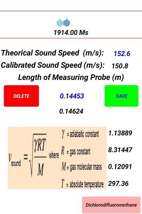
- Selecting the reference gas displays a screen indicating the theoretical physical parameters for that gas as well as its calculated sound speed based on the application of the gas sound speed formula.
- Using the above data the app calculates the length of the measurement cell, a value that can be saved by pressing the SAVE button (this value is kept by still turning off the mobil).
At this point the equipment is calibrated and you can start measuring the sound speed of the unknown gas sample.
Measurement
With the equipment already calibrated, we proceed to measure the speed of the sound and identify the unknown sample as follows (see disclaimer **):
- Open the measuring probe nozzles and slowly (low flow and pressure) fill the probe with the gas to be analyzed (do this operation in a ventilated site and, in the case of flammable gases, away from heat sources or open flames! Wear safety glasses and insulating gloves):
- As the measuring probe is filled, the value of the sound speed indicated on the initial display will change to stabilize at some value, at which point stop filling and close the nozzles of the measuring probe (depending on the filling speed this operation can last between 10 and 20 seconds).
- When you have a stable measurement allow the equipment to take 7 values and report an average value, at this point press the IDENTIFY button. A screen is then displayed showing the sound speed value measured as well as its coefficient of variation in addition to a list of possible identifications of the gaseous substance under study.
In this list, the candidate with a lower error % value will be the one to be taken as the most likely identification candidate. On this screen there is a button that allows you to copy the results to the mobile in image format (SCREENSHOT button).
Source: Measuring Refrigerant Gases Sound Speed Using Arduino and App Inventor 2