
Summary of FM Modulation/de-modulation Circuit
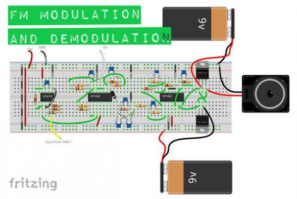
This article describes an educational FM modulation and demodulation circuit built using the Digilent Analog Discovery and Analog Parts Kit. The project modifies carrier and signal frequencies to pass audio files above 500Hz, utilizing op-amps and a voltage-to-frequency converter without actual radio transmission.
Parts used in the FM Modulation/de-modulation Circuit:
- 2 OP482 quad op-amps
- AD654 voltage to frequency converter
- 9 ceramic capacitors (39pF, 100pF, 1nF, 4.7nF, 10nF)
- 17 carbon film resistors (various values including 68, 1k, 6.8k, 10k, 20k, 47k, 100k, 470k)
- 1 1N4001 rectifier diode
- 1 speaker
- solderless breadboard
- jumper wires
- TIP31C NPN BJT (optional)
- TIP32C PNP BJT (optional)
- 2 9V batteries with clips
I got the idea for this circuit from one of my professors. That design wasn’t meant for passing frequencies high enough to be able to pass an audio file, e.g. 500Hz+, so I built this by modifying the carrier and signal frequencies, using only the Digilent Analog Discovery and the Analog Parts Kit. It should be noted that this circuit is primarily for educational purposes. Also note that there is no radio transmission here either. FM doesn’t necessarily mean radio waves have to be involved.
Throughout this Instructable I will be going through some of the functions and features of the Analog Discovery, but it will not be an exhaustive tutorial.
Step 1: Parts and tools
All of the parts listed below are provided in the Analog Starter Kit, except for the 9V batteries and clips. They should also be available through various online suppliers, local shops, or the salvage bin on your workbench.
The Parts:
– 2 OP482 quad op-amps (datasheet)
– AD654 voltage to frequency converter (datasheet)
– 9 ceramic capacitors: 2 – 39pF (39), 2 – 100pF (101), 2 – 1nF (102), 2 – 4.7nF (472), 1 – 10nF (103)
– 17 carbon film resistors: 1 – 68, 3 – 1k, 1 – 6.8k, 3 – 10k, 1 – 20k, 1 – 47k, 2 – 100k, 5 – 470k
– 1 1N4001 rectifier diode
– 1 speaker
– solderless breadboard
– jumper wires
(optional)
– 1 TIP31C NPN BJT
– 1 TIP32C PNP BJT
– 2 9V batteries with clips
The Tools:
– Waveforms software (free but required to run the Analog Discovery)
– short, free .wav file download. I used this one because it was awesome.
Pin-out diagrams are included for the OP482 quad op-amp and AD654 voltage to frequency converter, also called a voltage controlled oscillator or VCO.
Step 2: Designing
The schematic for this can be daunting to say the least. When I first started working with it, I got lost all the time and had to keep going back over it again and again. You’ll notice in the schematic that there are breaks throughout the design. Each of those breaks represents a good stopping point for verifying the circuit function. Take it slow and add one section at a time. The OP482 ICs are quad op-amps, meaning four op-amps on one piece of silicone. That can make it tricky to hook everything together as components can get crowded. This project can be built using individual op-amps if that is easier for you, but I would recommend using the OP27 and not the LM741. The LM741 should work, but I have had problems with it when it comes to needing fast, reliable response times. The specs are just a bit too slow for some applications, specifically the skew rate when you need high gain at a relatively high frequency.
For more detail: FM Modulation/de-modulation Circuit
- What is the primary purpose of this circuit?
The circuit is primarily for educational purposes. - Does this project involve radio transmission?
No, there is no radio transmission involved in this circuit. - Can I use individual op-amps instead of the OP482?
Yes, the project can be built using individual op-amps if that is easier. - Which op-amp does the author recommend over the LM741?
The author recommends using the OP27 because the LM741 response times are too slow. - How should I approach building the schematic?
You should take it slow and add one section at a time to verify function. - What software is required to run the Analog Discovery?
Waveforms software is free but required to run the Analog Discovery. - What specific components are included in the Analog Starter Kit?
All listed parts except for the 9V batteries and clips are provided in the kit. - Why was the AD654 component selected for this design?
The AD654 is a voltage to frequency converter, also called a voltage controlled oscillator or VCO.
