Hey guys what’s up.
Here’s something cool, a Naruto-themed Desk light that is made mainly from PCB. The heart of this project is an Attiy13A that drives some 0603 LEDs which are on the backside of the Face.
The Head part is detachable or swappable, which means we can prepare two or more Naruto Heads and add different color LEDs on the backside, then we can swap them for whatever light color we need.
I’ve modeled Naruto’s face in my PCBCad software and then send it to PCBway for samples.
After receiving the PCBs, I assembled the whole board and then added code to it and that is pretty much how I made this project.
In this Instructables, I’m gonna show you guys how I prepared this project in few easy ways.
so let’s get started!
Supplies
- Custom PCB
- Attiny13A
- 10K Resistor
- AO3400 Mosfet
- LEDs 0603
- switch
- USB Port
- 3D Printed Parts
- Li-ion cell
- Arduino as ISP Setup
Step 1: Basic Idea
So the idea here was to make a Naruto-Themed PCB Art kinda stuff.
To make this setup somewhat useful, I added LEDs on the backside so we can turn them ON whenever we like to use this setup as a dope Night Lamp. As for its working, Attiny13A is being used as the main MCU here.
Attiny13 Controls the gate of mosfet which turns ON or OFF LEDs.
The state of Mosfet is changed by pressing the button in a sequence.
- The first tap will put the setup in a FADE Sequence
- The second tap will keep this setup in HIGH Mode
- The third tap will reduce the Brightness by 50%
- The fourth tap will turn OFF the setup
Now let’s talk about the PCB Designing process of this board.
Step 2: PCB Design Process
So as you can see here, this PCB is not exactly normal.
The shape of this PCB is pretty different than the traditional Square or circular PCBs. At the TOP side, the Head is there and this rectangular part is the Driver board that will hold the head and keep the other components like MCU, USB Socket, Switch on it.
Also, this PCB is a breakaway PCB, which means we have to separate the Head portion and Base portion from each other by cutting this section with a cutter.
Step 3: SCHEMATIC
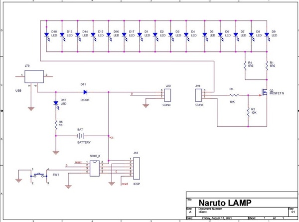
I placed all the LEDs with the Mosfet setup and a CON3 Header on the head.
On Base, I placed all the Important stuff like Attiny13A, USB Port Switch, and a CON3 Header pin. The plan here is to add Male and female Header Pins on both of the CON3 Pin.
By doing this, we can now remove or place the head on the base without any permanent solder joint.
This idea is pretty cool as we can now model a bunch of stuff from different movies or anime, we just need to place LEDs on them with a mosfet setup and when we connect them to base, they will work.
After finalizing the schematic and then making a perfect PCB, I send the Gerber data to a PCB Manufacturer for samples.
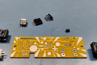
Step 4: Getting PCBs From PCBWAY
I uploaded the Gerber data to the PCBWAY’s quote page, I wanted to do something different this time so I choose the yellow solder mask, I generally get PCBs in white solder masks but this time I choose a yellow one as naruto hair is Yellow so getting yellow solder mask makes a lot more sense.
I received PCBs in a week and the overall PCB quality was great, which was expected as PCBWAY always offers quality stuff,
I’ve been using their PCB service for a year now, and my review of them is still the same, quality of PCBs is always high which is a plus point.
PCBWAY, well done you guys!
Check out PCBWAY for getting great PCB service at a less cost.
Step 5: Assembly Process
Next is the Assembly process of this Badge, which includes –
- solder paste dispensing process
- pick & place process
- hotplate reflow
- and THT components.
There is a total of 2 PCBs in this project and both have SMD and THT components.
First is the solder paste dispensing process
Step 6: Solder Paste
First, we place solder paste on each components pad, I’m using a generic solder paste (SN-Pb Ratio 63-37) with a solder paste dispensing syringe.
we first added the solder paste to the head and then on the base PCB.
Step 7: Pick & Place
Then we add components to their assigned place one by one. You could see the schematic for the precise location of each component.
Step 8: Hotplate Reflow
After adding components to their location, we carefully lift the PCB and put it on an SMT hotplate.
I made this Hotplate especially for making projects like these which require SMD soldering. hotplate available in the market were not exactly cheap so I made a minimal version of that which you can check out from here-
https://www.instructables.com/DIY-SMT-Hotplate-Pro…
But anyway, the hotplate heats the PCB from below up to the solder paste melting temp, as soon as the PCB reaches that temp, solder paste melts and all the components get soldered to their pads.
We carefully lift this PCB and try not to shake it as the solder paste is still melted and components might stray from their location if moved too much.
We lift the PCB and then place it on a cooler surface for a little bit, to cool down the heat of PCB.
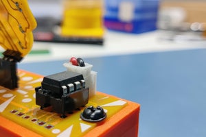
Step 9: THT Components
we add remaining THT components like the USB port, header pins, coin cell holder, and the power-off switch.
PCB is completed but it doesn’t work just yet as we still have to flash the attiny13A to fill it up with some sweet sweet lines of code.
Step 10: Code and Flashing Process
As for the Flashing Process, we cannot directly program ATTINY13 through any USB, I mean there’s a method for programming the Attiny straight from the USB port but I’m not doing that.
Instead, I’ll be using the ISP flashing method which will utilize the SPI Pins of attiny13 to burn the bootloader in it and then Flash.
Wire the Attiny85 with Arduino in this way.
- Vcc to Vcc
- GND to GND
- D10-RST of attiny
- D11- MOSI
- D12- MISO
- D13- SCK
(also right after uploading ISP Sketch to your Arduino, do not forget to add a 10uf Cap between Reset and GND pins of your Arduino board)
Instead of using an Arduino UNO and a breadboard for this job, I will use my DIY Attiny Programmer which I made for flashing the Attiny or Atmega MCUs. which you can check out from here for more details-
https://www.instructables.com/Multiple-ATtiny8513A…
Basically, we put the Attiny13 in the dip socket and flash the MCU with Arduino IDE.
Step 11: 3D Printed Body
This setup required a Box like Base body that can hold the Li-ion Cell inside and on the top side the circuit can be placed.
so I modeled this Body in fusion360 and then 3D Printed it on my Ender 3.
All the important print settings and STL files for this project can be downloaded from this project’s page.
but anyway, after getting the parts 3D Printed, all that was left to do was the final assembly.
Step 12: Final Assembly
Final assembly includes the following processes,
- First, we add Li-ion Cell inside the Base body and then add the circuit on it with two M3 Truss head screws
- Then we connect the battery onto the circuit with provided JST connector.
- In the end, we add Base Lid with four M2 Truss head screws, and the assembly is completed.
Now we can place the head on the base body and press the switch for initializing the whole setup.
Step 13: Result
We press the button and the LED sequence gets started, we press the button again and LEDs go into another mode. we press the button again and the LED then goes into another mode and this process will go on and on.
In the end, the result will look something like this!
Step 14: Addon
Also, we can prepare a Sasuke head with the same schematic, we can swap heads depending on which Night Lamp we need, naruto or Sasuke.
This is it for today, Leave a comment if you guys need any help, and I’ll be back with another project soon!
Also, thanks PCBWay for supporting this project, Check out PCBWAY for getting high-quality PCB Service at a less and economic cost. Peace out!
Source: Naruto Themed Night Lamp