Here you can find out how to make you very own n as made for the exhibition www.laplandscape.co.uk curated by art/design group Lapland.More images can be seen at flickr
This exhibition runs from Wednesday 26 November – Friday 12 December 2008 inclusive, and had a private view on Tuesday 25 November. Each participant has been asked to make a letter each of the ‘laplandscape’ portion of the web address. On the website each letter will link to related web contributions from each participant. This instructable is our web exhibit for this exhibition.
This n is an art work and experimental and these instructions should be treated as such!
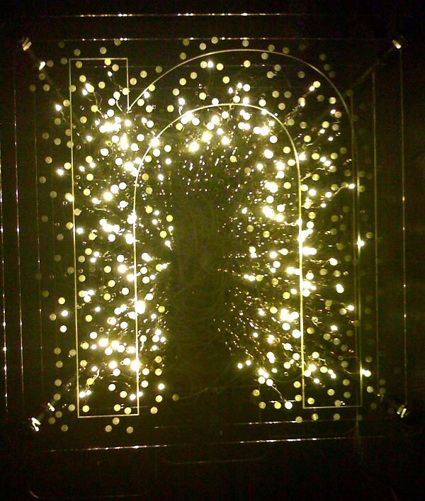
The n takes the form of 5 layers of laser cut acrylic, 3 of which have LEDs in them. The front panel has the outline of a letter n etched in it. 3 knobs control the LEDs and fade them between the ones inside and outside the outline of the n being on, on each layer.
There are no doubt simpler ways if wiring up the LEDs to do the same thing but, as all the exposed components etc are a big part of the aesthetic, we decided to do it this way.
Enjoy!
Step 1: Gathering parts
150 x LED’s – Yellow
150 x carbon film resistors – 0.5W 68ohm 5%
6 x transistors
3 x 22k pots
3 x knobs
1 x arduino decimila
4 x stripboard
pin stripStuff
5 x 3mm acrylic sheet 610mm x 610mm
small white cable ties
4 x 400mm M10 stud
38 x M10 nuts
4 x M10 dome nutsPower
1 x regulated power supplies 4.5volts 1400ma
1 x regulated power supplies 7.5 voltsConsumables
solder
super glue
araldite
Step 2: Gathering tools
soldering iron
damp sponge
solder sucker
snips
screwdriver
tape measure or ruler
strip breaker
work surface
‘steady eddie’multi-meter
hacksaw
spanner
cable stripper (though I prefer just to use the snips)
Step 3: Preparing artwork
In order to laser cut the acrylic sheets first you need to prepare the vector files. To do this we used Adobe Illustrator CS3, though any vector based software would suffice.
Files for each layer will be added below shortly, but the instructions explain how we made the files so that you could create your own.
The pdf file has the 5 layers saved and named as below
Front
Sheet 1
Sheet 2
Sheet 3
Back
Sizing
The first step is to measure the components that will be used, to make sure we create shapes the correct size. To do this we used a set of digital callipers.
Our 3mm LEDs were 2.9mm dia. The pots were 7mm. Holes to enable LEDs and attached wires to be pushed through easily from one layer to the next needed to be 5mm. Holes to take stud 10mm. And screw fixing “key hole” 15mm were at biggest and 6mm at smallest
Layout
Make sure you save your file at regular intervals. We called our source file source layers.
Next layout the basic shape in Illustrator. We are using a 400mm x 400mm square with rounded corners, radius 18mm. Centered within that is a lowers case n; font myriad overall height 337mm. This should be converted to outlines in the file. We specified a line thickness of 1mm and no fill. We then expanded the stroke to make it a solid object.
The 4 x 10mm dia. circles should be placed with the centre 20mm from top and side edge closest, so that they sit squarely in each corner.
This layer is named sheet front, and then duplicated and the new layer is named sheet 1.
Next work on sheet 1, but have sheet front visible but locked.
Save the file regularly.
Delete the outline of the n on sheet 1. Then place 50 x 2.9mm dia. circles within the outline of the letter ,and 50 x 2.9mm dia. circles outside the letter. Distribute them fairly evenly across the layer, but concentrate the ones outside the letter near the perimeter of the letter.
Duplicate sheet 1 and name the new layer sheet 2′. Hide and lock sheet 1. ‘
sheet 2 will be the next layer back in the sculpture. The circles on sheet 2 should be resized to be 5mm dia. These will be used to thread the wires through to the LEDs on sheet 1.
Place another 50 x 2.9mm holes within the letter and 50 x 2.9mm outside the letter on sheet 2. Distribute them evenly across the layer similar to before. Make sure that the new holes are not overlapping, or too close to, the previous ones.
This layer should then be duplicated and the new layer named sheet 3. Hide and lock sheet 2. The 2.9mm circles on sheet 3 should be resized to be 5mm dia. Then place another 50 x 2.9mm holes within the letter and 50 x 2.9mm outside the letter on sheet 3. Again make sure the distribution is fairly even and no holes overlap with previous ones.
Duplicate sheet 3 and call the new layer sheet back. Hide and lock sheet 3.
Delete all the holes except the 10mm ones in the corners on sheet back.
You now have the basic layout that will allow you to place a maximum of 300 LEDs over the 3 layers.
Details
We then added some further details. We selected all the holes on sheet 3 and copied them and pasted them onto sheet front. We then replaced each one with a little concentric circle pattern to act as diffusers in front of each LED. We expanded these in the same way as the n to create thick lines. On sheet 1, sheet 2, and sheet 3 we added a tab to each at the bottom for the pot and knob. We added a circle for the hole for the pot and a rectangle for the locating pin.
On sheet back we added keyholes to allow us to attach it to the wall with screws.
Saving
To save these drawings as separate files we saved the source file as sheet front.ai,sheet 1.ai, sheet 2.ai, sheet 3.ai and sheet back.ai using the ‘save as’ command.
These files were then opened and the other layers in the file deleted so that the file sheet 1.ai only has the layer sheet 1 in it and the file sheet back.ai only has the layer sheet back etc.
Step 4: Laser cutting preparation
To use the vector files created in the previous step with the laser cutter we had access to (laserpro 3000) we exported them as EPS files (version 8).Our laser cutter is located in our local Art School and many educational institutions have ones that will do work for members of the public at a cost. Look for places near you with engineering or product design courses if you want to try using one.
These instructions refer to the laser cutter we used, but most of the steps will be similar across many brands of cutters.
The EPS files were transferred to the computer attached to the laser cutter and opened in Corel Draw 13. This is what is used to print to the laser cutter.
In Corel Draw the cut lines in each file were set as ‘hairline’.
Then colours are selected for the objects to define the cut order. In this case anything black was cut first, red next, then green, yellow after that.
On sheet 1,sheet 2, sheet 3, and sheet back we set the internal pattern of holes to cut first, then the corner, pot, and keyholes holes next, then the outline of the whole piece last. The speed was set to 1.7% and power to 100%. The page size was set to just bigger than the whole drawing.
On sheet front we set the etching to go first, then the corner holes, then the outline of the whole sheet. Page set up was similar to other layers. The etch settings were 100% speed and 30% power.
In the printer page size setting we set the size to the same as the page size of the document and set it to ‘relative’ so that we could determine the zero-point to start cutting from.
NOTE: To select the correct power and speed settings for etching and cutting we first found the recommended levels for this machine and 3mm acrylic, and then did ‘bracketed’ tests either side of these figures on a spare bit of acrylic. It is always worth testing, as machines can vary over time and with use.
Step 5: Laser cutting
We placed the first piece of acrylic on the bed of the laser cutter and then focused the cutter. We set the cutter head to just inside the top left corner of the bit of acrylic. A red dot of light on the material you are cutting shows where the head is set to.
Then the lid gets closed, the extractor started to remove any fumes during cutting, and the file is printed from the Corel Draw document to the laser cutter ‘printer’, using the print preview to do a last minute check before printing. The file then spools to the laser cutter and details of it appear on the screen on the front of the machine.
If the cutter is focused, lid down, and extractor on, then you can now press start and the laser cutter will start cutting your file. Once it has finished switch off the extraction and open the lid to retrieve the acrylic. On this machine we pressed delete and delete to remove the file before sending the next file to print.
We repeated with each of the further 4 files until all layers were cut and etched. You should re-focus the cutter each time to ensure a correct cut.
The etching took around 50 minutes to complete. The cut sheets around 8, 10, 13 and 4mins.
Then, handling them using white cotton gloves, we cleaned the sheets with a window cleaning spray to remove finger prints and other marks.
Step 6: Electronics
The next step, now you have the acrylic sheets, is to make up the LEDs and control circuits.We decided to put 50 LEDs on each layer not the full 100 that we have enough holes for. After testing we decided 50 was enough and liked the way that the LEDs reflected internally within the acrylic to light up the ’empty’ holes, but you could do the full 100 on each sheet if you wanted.
stripboards
First use the “strip cutting tool” to create the breaks on the strip board as needed.
Next solder 50 resistors in two groups of 25 at each end. In each block of 25 we did them in smaller blocks of 5 for spacing purposes.
Now solder the 2 transistors onto the strip board.
Then run a line of solder down the board to join all the strips with resistors to each other and to where the positive supply will come in. You could also do this with wire if you prefer, joining each strip to the next.
Next solder the transistors onto the stripboard.
After that use a multimeter to make sure that there are no short circuits between strips. Then do a multimeter test to check that all the resistors were soldered correctly by putting one contact on the positive line of solder and the other on the other side of the resistor.
Then cut the wires, you will need 100 wires for each 50 LEDs. We used yellow and white to differentiate between positive and negative. We cut the wires for the sheet 3 to 300mm each, for sheet 2 and sheet 1 we cut them to 800mm.
The yellow wires should be soldered to the positive side of the circuit, beyond the resistors. The white ones are soldered in a cluster in the area not connected to the positive line of solder.
Having attached all the components to the strip board, now solder the LEDs to the ends of the wires. Yellow to the long pin, white to the short pin (and flat edge). We shortened the length of the pins before doing this, making sure to keep the pins different lengths so we knew which side was which.
Repeat another two times so that you have three identical boards.
Step 7: Arduino program
Next we need a way of controlling the LEDs.
We used an Arduino development board, as we have been playing around with them a bit for various projects.
Initially download and install the arduino software, which is available for; Windows, Mac OS X, Linux (32bit) and Linux (AMD 64bit).
After installing we used the following code:
(download the .pde file below)
opening ‘n’ version 1.2
3 sets of 2 led’s fadding from one to other via pot
*/
int ledPin1a = 11; //led 1 a
int ledPin1b = 10; // led 1 b
int ledPin2a = 9; //led 2 a
int ledPin2b = 6; // led 2 b
int ledPin3a = 5; // led 3 a
int ledPin3b = 3; //led 3 b
int PotPin1 = 1; //set variable to value of analog pin 1
int PotPin2 = 2; //set variable to value of analog pin 2
int PotPin3 = 3; //set variable to value of analog pin 3
 int value1 = 0;
int value2 = 0;
int value3 = 0;
int ledValue1a = 0;
int ledValue1b = 0;
int ledValue2a = 0;
int ledValue2b = 0;
int ledValue3a = 0;
int ledValue3b = 0;
void setup()
{
pinMode(ledPin1a, OUTPUT);
pinMode(ledPin1b, OUTPUT);
pinMode(ledPin2a, OUTPUT);
pinMode(ledPin2b, OUTPUT);
pinMode(ledPin3a, OUTPUT);
pinMode(ledPin3b, OUTPUT);
Serial.begin(9600);
value1 = analogRead(1);
value2 = analogRead(2);
value3 = analogRead(3);
}
void loop()
{
value1 = analogRead(PotPin1); //read value of PotPin1
ledValue1a = value1 /=4;
ledValue1b = 255 – ledValue1a;
analogWrite(ledPin1a, ledValue1a);
analogWrite(ledPin1b, ledValue1b);
value2 = analogRead(PotPin2); //read value of PotPin2
ledValue2a = value2 /=4;
ledValue2b = 255 – ledValue2a;
analogWrite(ledPin2a, ledValue2a);
analogWrite(ledPin2b, ledValue2b);
value3 = analogRead(PotPin3); //read value of PotPin3
ledValue3a = value3 /=4;
ledValue3b = 255 – ledValue3a;
analogWrite(ledPin3a, ledValue3a);
analogWrite(ledPin3b, ledValue3b);
Serial.print(ledValue1a);
}
//works nice, straight fade, one high other low.
This then needs to be uploaded via USB to the arduino board. Having the serial.print function enabled means that it is possible to see the value being created by pot 1 which is good for testing and debugging.
Having completed upload and testing you then unplug the USB and move the jumpers to enable the arduino to use a external power supply rather than the USB.
For more detail: N: how to make a multi-layered acrylic and LED sculpture with variable lighting levels