Mug-O-Matic is a one of a kind DIY toy, a real 3-axis Tiny CNC drawing robot that can customize coffee mugs!
This capable little robot can draw anything you want via manual control, bluetooth, calculated algorithms, or even g-code. So you can enjoy your custom mug creation, then wipe it clean and draw something totally different every day and never have the same thing twice!
The intent of this project is to produce fun and accessible educational tools. We want to encourage & inspire people to engage in tinkering and making things, because the creative process is a powerful way to learn.
To best serve that purpose, these robots are designed with hackable open source hardware and are controlled by free open source software. Building this bot offers an opportunity to experiment with 3D printing & useful software such as Processing, Repetier Host, Slic3r, and of course Arduino – the most common and universally applicable microcontroller for physical computing. So knowledge gained playing with this toy is transferable to real life applications!
As of this writing we are preparing for a crowdfunding on CrowdSupply.com in the coming weeks. The TinyCNC robots require the use of a custom PCB & numerous random components so the easiest way to reproduce this work is to pledge support & receive a kit early next year.
The kits we offer are self-sufficient and contain all the hardware & tools necessary. No soldering or bread-boarding is required; controls are plug-&-play. And like all EngineerDog.com projects, these items are supported with great online instructions such as this one!
As you can see in the promotional video below, there are many possible robots you can build using the same core control elements. To keep things simple this instructable will focus on assembly, wiring, & controls of the Mug-O-Matic robot specifically.
This robot is of moderate difficulty to build and operate. If you are interested in a similar but less challenging toy, check out the Desktop Sentry. (Separate Instructable for that coming soon!)
Step 1: THE BIG PICTURE
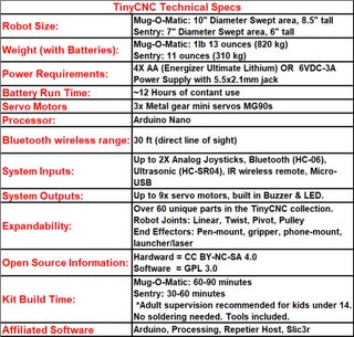
Mug-O-Matic is driven by arduino nano & a custom PCB breakout running 3 metal geared mini hobby servos. The device sits on top of a specific 11 Oz coffee mug and uses a sharpie to draw on the side. The image will remain their until you manually remove it with a warm soapy wash or a magic eraser.
Mug-O-Matic’s primary means of interface are a joystick & bluetooth module for fiddling around, and a usb tether to your computer for 2 way communication to make detailed drawings from user created gcode. Drawings typically take 1-10 minutes depending on complexity and the device is mesmerizing to watch the whole time, just like a 3D printer.
The drawable resolution is 0.3mm with great repeatability in terms of being able to trace the same lines over & over. That resolution is more than adequate for novelty purposes however I would not classify this device as anything more than toy.
The TinyCNC collection has 60+ parts and 2 major recurring design patterns:
- The Snap on Lid– No tools required to swap PCB enclosure cover.
- The 20mm screw hole pattern– Enables different modules to be screwed together.
This robot is powered by 4x AA batteries and I only recommend using Energizer Ultimate Lithium batteries. These batteries have a high constant voltage that doesn’t sag under load or as it nears end of life. (Data sheet here.) They are a little more expensive up front but they dramatically improve performance and last long enough to make the upfront price worth the trade off. (In any case do not use rechargeable batteries since they operate at a lower voltage & performance will suffer.)
REQUIRED SOFTWARE DOWNLOAD LINKS TO PROCEED:
Arduino IDE (Arduino User Interface)
NotePad++ (Strongly recommended for viewing/editing/saving code)
Github.com Repository (Released programs for Mug-O-Matic & Post-It-Plotter drawing robots)
RepetierHost + Slic3r for converting the model into gcode. (Required)
Processing for sending commands line by line from computer over usb. (Required)
Step 2: GATHER PARTS, MATERIALS, & TOOLS
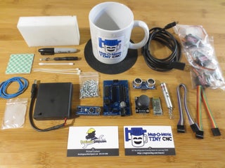
PARTS & MATERIALS:
Full Bill of Materials linked here. If you just want to tinker & source everything yourself please note that the collection is designed around the TinyCNC PCB and a specific mug so that much you’ll need from me.
Mug-O-Matic has 17 unique 3D printed parts, all printed from rigid PLA-Pro plastic or from flexible TPU. An updated folder of 3D printable parts is saved here:
If you have your own 3d printer you can get a ‘maker kit’ and print out your own plastic parts. Attached are the STL files in a zip doc, please note all parts must be printed with: 0.4mm nozzle diameter, 0.2mm thick layers, 4 perimeters, 10% infill, and be printed in the orientation they appear by default. No supports needed. eSun PLA+ is the preferred material for all parts except the ‘bracket-flex-limiting’ which is to be printed from shore 95A TPU material at the same print settings as above. If you don’t want the hassle of printing then you can pick up a complete kit from me!
TOOLS:
*Plastite Screws: The TinyCNC collection is held together using a single size of screw to make things easy! This ‘plastite’ screw type forms its own reusable threads as you drive it in. For this reason it can be hard to drive in the first time so I recommend pre-screwing all your holes to form the thread before assembling parts together so you don’t have to drive them from funny angles during assembly.
*Phillips Screwdriver- size #2.
*Driver Handle- (3D Printed)- A handle that sticks on the back of the driver to give you more grip. Its note that it is a separate part for times when you want the screwdriver to be smaller. The back side of the handle is also shaped to help you install servo horns.
*Magnet- Tiny screws are easy to drop so a magnet (included in the kit) attached to the driver makes your life much easier!
*Grease- For all surfaces that make sliding contact we want to add the thinnest sheen of grease. I recommend spreading a pea-size using a paper towel to apply it between the two surfaces that will move against each other. Wipe the grease into the crevices and then wipe off 90% of excess and basically just leave a shiny surface behind! It will feel wasteful but in this application too much grease can have an unintended effect like walking through deep mud!
*Tweezers- (3d Printed)- Used to grab and pull cables through small slots. The screwdriver can also be installed inside the tweezer hole to make a friction ratchet so you can drive it from the side as well.
Step 3: Setup Arduino & Center Servos
To get started well need to unpack the arduino & get connected to a computer. The hobby servos need to be set to their center position electronically prior to assembly so everything is where we think it is.
The code we will use for everything Mug-O-Matic related is all in the same arduino sketch. We just (un)comment out certain functions when we want to do different things. At the github repository, in the GCODE READER folder there is a sketch called “Arduino_Code_Gcode_Reader”.
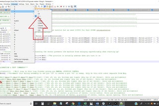
Copy its contents and paste them into notepad++. Make sure the language of notepad++ is set to C++ so the syntax corrections it suggests will be relevant. Then uncomment the “AssemblyAid()” function located in the Setup section by deleting the two forward slashes in front of it. This function contains a permanent loop so the program will be stuck doing the assembly command.
This function sets your servo pin s8 to follow a sweep motion (for testing purposes) and pin s9 to go to the center position for assembly purposes.
Any time I say Center your Servo I am saying plug your servo in and power on the arduino to center it. You can leave it powered on while you assemble it BUT BE CAREFUL! These servos are small and you can break them if you try force them against their will while they are powered on!
Copy and paste the code from notepad++ into the arduino IDE. Make sure your nano is connected to the computer via usb and that your arduino IDE connection settings are correct as shown in the picture. Upload the code. (Note the batteries can be set to ON or OFF for this, but if they are on beware the arm swinging around.)
See Picture attached for PCB Pinout Diagram for reference. Note the servo motor cables are color coded and will not move if connected in reverse, see attached picture.
Step 4: First Linear Actuator Assembly: Y-axis
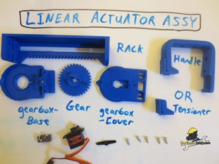
Use the screws that come with the servo to attach it to the top of the gearbox cover.
Remember to lightly grease the surfaces that will have sliding motion, this includes:
- The bottom face of the gear and the bottom of the gearbox cover.
- The 4 pockets in the gearbox base on the posts that the rack will straddle.
- The tensioner/handle surface that will touch the back rack wall
Center the servo electronically, then attach the horn & gear oriented vertically as shown by pressing it on with the press tool/screwdriver handle. Use the machine screw in the center of the horn, screwing it down snugly, then once again use the last tiny pointy screw in the servo bag to secure the horn to the gear to prevent wiggle. Verify motion is smooth with the S8 pin sweep function.
Now drop the rack onto the gearbox base and center it. Then drop the servo cover assembly into place so that the center gear tooth on the rack falls into the center valley on the gear while the servo motor is set to the center position. This will properly clock the system.
Attach 3 plastite screws snugly (Do not over tighten these) to hold everything together. Verify with the sweep function that the rack moves smoothly. It if stalls or is jerky then barely loosen the two plastite screws in the rack.
The final part is the tensioner which we use to get the last bit of wiggle out of the system. It is held in place with 1 vertical snug plastite screw. And finally, screw in the screw set at a 45 degree angle in the tensioner to flex the wall out until it is touching the rack with the rack in the center position. It will not need to be scrwed in all the way, just enough to touch to prevent wiggle. Use the sweep function to verify smooth motion at the very end.
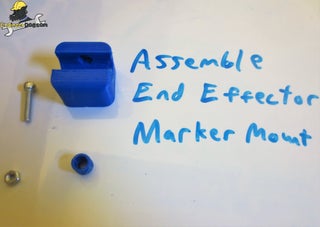
Step 5: Assemble End Effector & Flex Bracket
These parts attach to the Y axis actuator you just built. Note part orientations in the images as they are important.
To assemble the end effector gather the m4 cap screw, the m4 nut, and the plastic parts shown. Place the screw into the round plastic knob and loosely press it into place.
Then use the tweezers to hold the m4 nut in the inside of the plastic marker mount and use the m4 cap screwto catch it and pull it into place. Use the leverage of screwing the m4 cap screw all the way down to press the nut & knob firmly into their places.
Mount the end effector to the actuator in the orientation shown using two plastite screws positioned diagonally from each other in any of the 4 holes. (We only need 2 for a firm connection. If it helps you can temporarily remove the tensioner from the last step to make room for your screwdriver to do this.)
Next use the tweezers to load up 4 plastite screws into the flexible bracket. Then mount the bracket such that the end with the slit is pointing toward the end effector. (See cad image) To access the screws inside the bracket you stick the screwdriver through the holes in the bracket, see pics.
Step 6: Build Mug Lid Assembly X-axis
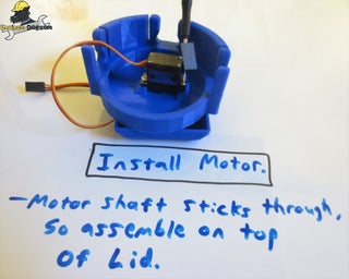
Grab the parts shown and mount your X-axis servo. Note the shaft end sticks out a bit so it can help to set your assembly over a gap while you screw things down.
We are going to mate the two big plastic pieces together at a specific orientation but first apply a thin layer of grease between the two surfaces that will be in moving contact.
Then with your servo centered, line up the two notches on the sides of the parts as shown BEFORE pressing on the horn and screwing it down with the machine screw. You will need to use the head & handle of the screwdriver to get the horn pressed on.
Screw the machine screw all the way down to a snug seat. Then use the last remaining tiny pointy screw from the servo bag and screw it into one of the horn holes firmly, making sure it goes all the way it. This screw assures that the horn is attached to the plastic part is sits in.
Plug your servo into pin s8 to do a sweep motion check. The movement should be smooth and not jerk around or stall (jerking means the machine screw is too tight!). The assembly should also be tight and not wiggle freely.
Step 7: Second Linear Actuator Assembly: Z-axis
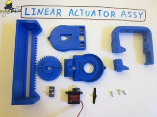
Same exact procedure as the first linear actuator assembly with 2 exceptions.
1. Per pics 5-7 on this step, you have to route the Z axis servo cable through the groove under the rack prior to screwing down the 3 plastite screws that hole everything together.
2. At the very end leave the handle/tensioner off for now. It will be in the way for the next step.
Step 8: Join the Sub-assemblies
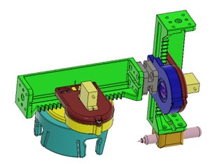
(I used cad here because I changed the order of operations later to make it easier for you.)
Mount the two assemblies together oriented as shown. Use all 4 plastite screws to attach the rack end to the flexible bracket. Screw down snugly but not overtighten at the risk of stripping out the hole.
Now you can add the mount the handle as shown. (it would have been in the way if you did it first.). Then adjust the tensioner on the handle to bring it into contact with the rack to prevent the rack from wiggling. Use the sweep function to verify that you have achieved smooth wiggle-free motion.
Note you can also add holder to hold up to 4 sharpies to the handle but that component is not going to be included in the kit.
Source: Mug-O-Matic: a Modular Tiny CNC Drawing Robot!