Summary of Motion Activated Automatic LED Stair Lighting With Arduino
This project is an Arduino-based automatic LED stair lighting system ("the stair butler") that improves safety by activating LED strips using a PIR motion sensor only when ambient light is low. The LEDs fade on and off smoothly controlled by a MOSFET, with multitasking Arduino code managing motion detection, light level sensing, and LED fading simultaneously. The light sensor ensures activation only in darkness. The design is adaptable for night lights, security, and courtesy lighting. Detailed wiring, testing, and installation instructions are provided, including safety tips for handling 12V power and Arduino integration.
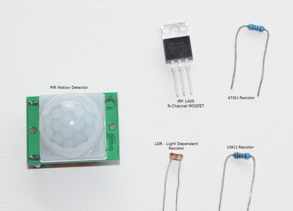
Parts used in the Motion Activated Automatic LED Stair Lighting with Arduino:
- Arduino (Leonardo or similar)
- 12V LED light strip (approx. 1.4m, 0.5A)
- 1 Amp 12V DC power supply with 2.1mm barrel jack
- N-Channel MOSFET (IRF-1405 or IRF540N)
- PIR motion detector (HC-SR501 recommended)
- LDR (Light Detecting Resistor) photo detector
- 10K Resistor (Brown, Black, Black, Red)
- 470 Ohm Resistor (Yellow, Violet, Black, Black)
- Breadboard
- Hookup wire
- Prototyping board (optional for permanent setup)
- 2-way screw terminal block (for LED strip connection)
- 3-pin header (for PIR connection)
- Solder and soldering iron (optional for permanent setup)
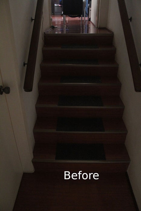
I built this Arduino based automatic LED light controller for a set of poorly lit stairs in our new home. The stairs are quite dangerous – especially at night – but not any more thanks to the Motion Activated Automatic LED Stair Lighting with Arduino (a.k.a. “the stair butler”).
By carefully positioning the LED’s and PIR sensor, this project could easily be adapted into:
- A night light for a baby’s room – LED under crib, PIR facing door. This is especially handy when checking on baby at night time and you do not want to turn on the room lights (or you are carrying baby).
- A courtesy lamp for the elderly
- A welcome home at night light – position LED’s in the entry hall with sensor facing the door. LED’s turn on automatically when you open the front door.
- A security light. By adding a WiFi module, you can get it to report when the lights came on and/or when motion was detected. Capture data on a computer and analyse it as you see fit.
- Many other scenarios where automated lighting (or with a WiFi module) remote monitoring and/or control is required.
This relatively simple project uses a PIR motion sensor to detect people (and cats) approaching the stairs. When it detects someone approaching, the LED light strip is turned on. The LED light strip is controlled via a MOSFET and features a rather cool “fade on” and “fade off” effect. The project illustrates how to control a 1 Amp 12 volt power feed using one of the Arduino’s 5 volt digital pins digital pins. Finally, there is a light level sensor which is used to ensure that the LED’s are turned on only when it is dark enough to warrant doing so.
The Arduino controlling program (sketch) uses a form of mulit-tasking known as cooperative multitasking. This allows me to to manage fading the LED’s on and off while simultaneously detecting movement via the PIR motion detector and reporting light levels. The value add is that it is relatively simply to detect new motion while fading the lights off and simply fade them back on again without too much complexity. This cooperative multi-tasking technique can be used for any project where you need things to happen independently but at the same time.
The Arduino source can also be obtained from GitHub account at:
Step 1: What You Will Need
You will need the following parts
- One Arduino. I used a Leonardo, but any should work.
- One LED light strip (not shown in the photo). This should be 12 volts or less as the Arduino will also be powered by the LED light strip’s power supply through the Arduino’s external power jack. Mine is about 1.4m long and draws about 0.5A when turned on.
- One 1 AMP 12-V DC power supply with a 2.1mm Barrel jack suitable to plug into your Arduino.
- One N-Channel MOSFET. I used IRF-1405. I also tried IRF540N. Both worked just fine.
- One PIR motion detector (mine is a HC-SR501 PIR).
- One LDR (Light Detecting Resistor) photo detector
- One 10K Resistor (Brown, Black, Black, Red, and any other colour)
- One 470 Ohm Resistor (Yellow, Violet, Black, Black and any other colour)
- One breadboard
- Hookup wire.
If you wish to make a more permanent setup, then I would recommend getting a second set of parts 1 through 7 from the above list – plus:
- One prototyping board
- Wire to connect the components
- One 2 way screw terminal block (for connecting the LED strip)
- One 3 pin header (for connecting the PIR).
- Solder and Soldering Iron
It is not strictly necessary to get the second set of parts, but in my circumstance I find it easier to have two setups of the project. One setup is connected to my computer so I can test revisions of the program. Once I’m happy with any changes I’ve made, I can then upload the updated code to the equipment installed at the stairs.
Optionally, for initial testing, you might consider not using the 12 volt supply. In this case simply temporarily substitute the MOSFET and LED light strip with a single LED + 470 ohm resistor. Once you get the project running, just replace the 470 ohm resistor + LED with the MOSFET + LED Strip.
Step 2: Hook Everything Up
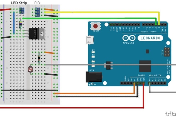
Connecting the bits together is relatively straight forward. Apart from the power connections, there are three main parts to the circuit:
- The motion detector (Pin 2 on Arduino)
- The LDR light level sensor (Pin A0 on Arduino)
- The LED control (Pin 3 on Arduino)
Important note: The LED strip is powered from a 12V power source. This will be extracted from the VIN pin on the Arduino. You must be careful to never connect the 12V power source to any of the other Arduino pins. If you fail to keep the 12V separate from the other pins, the “magic smoke” that makes electronic stuff work might escape. If your “magic smoke” escapes, your Arduino probably will not work anymore and may even damage your computer if it is connected via USB.
Note: LED light strips are typically 12 volt. The Arduino will not be able to supply enough power (voltage or current) directly to turn on an LED light strip. For initial testing, you can remove the 12 volt light strip and MOSFET and simply connect a single LED with a 470 Ohm resistor between Pin 3 and Ground.
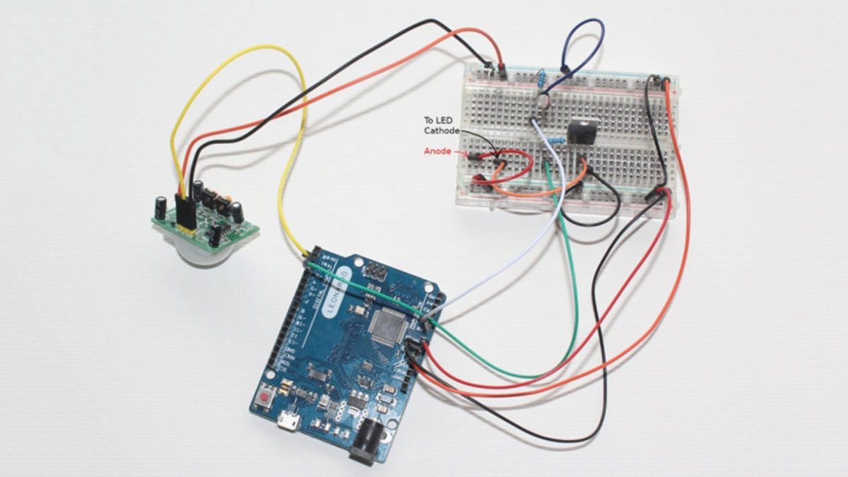
Hook up your components by following the wiring diagram shown above and/or follow the instructions below. The wire colours correspond to the wiring diagram shown above.
Power connections:
- 12V supply (VIN) to one of the power rails on your breadboard (red wire)
- 5V supply (5V) to the other power rail on your breadboard (orange wire)
- Ground (GND) to one of the ground rails on your breadboard (black wire)
- Connect both of the ground rails on your breadboard together (black wire)
Light level sensor:
- Insert your LDR and 10K resistor (Brown, Black, Black, Red) so that one of the LDR’s leads is connected to the one of the resistor leads.
- Connect the point where the LDR and resistor are connected to A0 on the arduino (grey wire)
- Connect the other end of the LDR to the ground rail
- Connect the other end of the 10K resistor to the 5V rail (orange wire)
Note when mounting the LDR, ensure it is facing into your stair well. If it isn’t positioned in this way, it may detect ambient light from another location that isn’t flowing into the stair well. In this case, the LED might not always turn on when you expect it to as there is a lot of ambient light near the sensor – even though the stair well is dark.
PIR Motion Detector:
- Connect the Power pin on the PIR to the 5V rail on the breadboard (Orange wire)
- Connect the Ground pin on the PIR to the GND rail on the breadboard (Black wire)
- Connect the Signal pin on the PIR to pin 2 (D2) on the Arduino (yellow wire)
Ensure the PIR can “see” into the stairwell area so that only movement in or towards the stair well activates the LED’s.
MOSFET and LED Strip
Beware: this is the only step where the 12 volts meets the 5V. Actually the 12V and 5V never actually meet because inside the MOSFET, the 5V signal (which is connected to the MOSFET’s gate) is insulated from the rest of the circuit (i.e. the 12 volt parts connected to the MOSFET’s source and drain). This Wikipedia article explains the basics of how the MOSFET works and shows the insulating layer between the gate and the rest of the components.
- Insert the MOSFET into your breadboard.
- Connect the Gate Pin to the 470 ohm resistor. Check the datasheet for your MOSFET to determine which pin is the Gate.
Assuming you are using the same MOSFET as me, the Gate Pin is most likely the one on the left when you hold the MOSFET so that the heat sink is on top and the writing on the case is facing you. - Connect the other end of the resistor to Pin 3 on the Arduino (Green wire)
- Connect the MOSFET’s drain (most likely the middle pin and heat sink) to the Cathode of the LED strip (blue wire)
- Connect the MOSFET’s source (right pin when holding the MOSFET as described above) to GND (black wire)
- Connect the Anode of the LED Strip to the 12V rail (red wire)
Check your connections
Once you’ve connected everything up, take a break, then double check your connections. Remember if you incorrectly connect any of the 12 Volt (VIN red wire) connections to the rest of the circuit you will probably release the “magic smoke” and that will be bad for your Arduino.
Step 3: The Code
Following is the entire program. Simply copy and paste it into a new project in the Arduino IDE. No special libraries are required, so there is no need to download anything else.
/******************************************************************************
 * Automatic Stair light controller
 *
 * Detects motion via a PIR (pin 2 digital) and gradually turns on an LED Light strip (pin 3 digital).
 * When motion ceases the LED light strip is gradually turned off.
 *
 * An LDR (Analog A0) is used to detect ambient light levels. The LED is only turned on if the ambient
 * light level is lower than a specified threshold.
 */ Define a constant that determines at what light level should
// should the LED strip be turned on. If the light level is above
// this threshold, the LED strip will not be turned on when motion is triggered.
#define LIGHT_ON_THRESHOLD 200// The pins to which the various peripherals are connected.
int pirPin = 2;             // Input: The signal from the PIR.
int ledStripPin = 3;        // Output: PWM signal to the MOSFET.
int lightSensorPin = A0;    // Input: The reading from the ligh sensor (LDR)// Cooperative multi-tasking data.
// Cooperative multi-tasking works by activating a task from time to time.
// The period of time between activations depends upon the task.
// This variables is used to track the point in time that we last checked the
// Arduino clock. Our main loop will continually check to see if the Arduino's clock
// has ticked over (> 1ms has passed since we last did anything). If it has, then
// the individual tasks are checked to see if it is time that they should be activated.
//
// You can visually see this working if you activate the Serial monitor in the Arduino IDE.
// What you will see is that the ambient light level reporting will seemingly randomly appear
// in amongst any other debugging messages you might add to the program (e.g. outputting the
// brightness level during a fade).
//
unsigned long timePrev = 0;// Multi-tasking sub tasks:
// - Read the PIR once every 10 ms.
// - If turning on the LED's, adjust the brightness ever 10 ms
// - It turning off the LED's, adjust the brightness every 30 ms
// - Report the light leveel once every second (this is primarily for testing).
#define PIR_TIME 10               // Check the PIR every 10 ms
unsigned int pirReadTmr = 0;      // A counter to measure how long since we last checked the PIR#define FADE_ON_TIME 10           // LED's "fade on", the brightness is increased every 10 ms.
#define FADE_OFF_TIME 30          // LED's "fade off", the brightness is decreased every 30 ms.
unsigned int faderTime = FADE_ON_TIME;  // will be set to either FADE_ON_TIME or FADE_OFF_TIME depending upon
                                        // whether we are turning the LED's on or off.
unsigned int faderDelayTmr = 0;   // A counter to measure how long since we last adjusted the LED brightness.#define LIGHT_CHECK_TIME 1000     // Check the ambient light level once every 1000 ms (once per second)
unsigned int lightCheckTmr = 0;   // A counter to measure how long since we last reported the ambient light level./*****************************************************************************
 * Setup:
 * - Initialise the Serial comm's just in case we are debugging/testing.
 * - set up the MOSFET (ledStripPin) and builtin LED PIN to output
 * - Initialise the multi-tasking timer (timePrev),
 */
void setup() {

  Serial.begin(9600);
  int cnt = 0;
  // Wait for the the Serial port to initialise (but don't wait forever)
  while (!Serial && cnt < 100) {
      cnt++;
      delay(10);
  }
  // Set the digital outputs (LED_BUILTIN and LED Strip MOSFET)
  pinMode(LED_BUILTIN, OUTPUT);
  digitalWrite(LED_BUILTIN, LOW);
  pinMode(ledStripPin, OUTPUT);  Serial.println("Ready");  // Initialise the time Keeper
  timePrev = millis();
}/*****************************************************************************
 * Loop:
 * - Check to see if the time has changed.
 *   - If the time has changed, work out how long has elapsed since the last
 *     time we checked (should always be 1 ms)
 *   - Update the 3 sub-task time counters.
 *   - Check each sub-task time counter to see if it has passed it's respective
 *     threshold.
 *     - If we have passed the threshold, call the appropriate sub-task.
 *     - reset the appropriate time counter to 0.
 */
void loop() {  // Get the current time in millis.
  // Note that the value is unsigned long. If you do not use unsigned long, then
  // after a few days your multi-tasking might "freak out" (the technical term for
  // not performing as expected).
  unsigned long timeNow = millis();  // Has the time progressed since last time we checked?
  if (timeNow != timePrev) {
    // Yep, so work out how long has passed (normally 1 ms)
    unsigned int delta = timeNow - timePrev;
    // Capture the current time so we can check if time has moved on from "right now".
    timePrev = timeNow;    // Update the sub-task time counters.
    pirReadTmr += delta;
    faderDelayTmr += delta;
    lightCheckTmr += delta;    // Has the pir timer passed it's threshold? If so, check the PIR.
    if (pirReadTmr >= PIR_TIME) {
      processPir();
      pirReadTmr = 0;
    }    // Has the fader timer passed it's threshold? If so, adjust the brightness of the LED's
    if (faderDelayTmr >= faderTime) {
      processFade();
      faderDelayTmr = 0;
    }    // Has the ambient light level timer passed it's threshold? If so, report the ambient light level.
    if (lightCheckTmr >= LIGHT_CHECK_TIME) {
      processLightCheck();
      lightCheckTmr = 0;
    }
  }
}/*****************************************************************************
 * Multi-tasking sub tasks start here
 */
 // Variable to track the last known state of the PIR - initially this should be OFF.
int pirState = LOW;// Variables to track what the LED control is doing.
bool fadeDisabled = true;     // Are we fading? true = NO, false = YES
bool fadeUp = true;           // Which direction are we fading? true = ON (i.e. getting brighter), false = OFF (i.e. getting dimmer)
int brightness = 0;           // The current brightness. Initially the LED's are off, therefore the brightness is 0./*************************************
 * Process PIR
 * - Called when it is time to check the PIR to see if it has changed state.
 * - If the PIR has changed state, initiate the appropriate action for the LED.
 *
 * Note. It is possible that the PIR will report that "motion has stopped". This might happen
 * part way through the LED turning off cycle. If this occurs, then the fadeOFf will immediately be
 * stopped and the fadeOn will be initiated.
 * This could happen if someone moves out of sight of the PIR, but returns shortly after the PIR
 * stops reporting motion.
 * The overall result is the that the LED's will smoothly transition from whatever brightness level
 * they happened to be at back to full brightness with no ugly blinking, flashing or sudden jump to
 * an extreme level of brightness.
 *
 * While the above scenario can be handled without multi-tasking, it is much easier (IMHO) to do with
 * this form of multi-tasking. That is checking the PIR state changes while simultaneously adjusting the
 * LED brightness (and as it happens, simultaneously reporting the ambient brightness once every second).
 */
void processPir() {
  // Read the PIR and see if it's state has changed from last time we checked.
  int val = digitalRead(pirPin);
  if (val != pirState) {
    pirState = val;         // PIR state has changed, so record this new state for subsequent state change checking.
    if (pirState == HIGH) { // Has the PIR detected motion?
      Serial.println("Motion Detected");        // Yep!
                            // Signal that motion has been detected by turning the BUILTIN_LED on.
      digitalWrite(LED_BUILTIN, HIGH);
                            // Determine if we need to turn on the LED Strip.
                            // we will turn on the LED strip if:
                            // a) the ambient light level is less than the LIGHT_ON_THRESHOLD, or
                            // b) the current state of the LED's is on (brightness > 0)
      if (getLightLevel() < LIGHT_ON_THRESHOLD || brightness > 0) {
        fadeOn();           // initiate the turn LED's on sub-task
      }
    } else {                // Motion no longer detected.
      Serial.println("Motion ended");
                            // Signal that motion is no longer detected by turning the BUILTIN_LED off.
      digitalWrite(LED_BUILTIN, LOW);
      fadeOff();            // initiate the turn LED's off sub-task
    }
  }
}/*************************************
 * Fade On
 *   Initiates the turning ON of the LED strip.
 */
void fadeOn() {
  fadeDisabled = false;       // Enable the fader sub-task.
  fadeUp = true;              // Set the direction to "turn on LED's" (i.e. "get brighter").
  faderTime = FADE_ON_TIME;   // Set the timer threshold that controls how frequently we increase the brightness.
}/*************************************
 * Fade Off
 *   Initiates the turning OFF of the LED strip.
 */
void fadeOff() {
  fadeDisabled = false;       // Enable the fader sub-task.
  fadeUp = false;             // Set the direction to "turn off LED's" (i.e. "get dimmer").
  faderTime = FADE_OFF_TIME;  // Set the timer threshold that controls how frequently we decrease the brightness.
}/*************************************
 * Fader sub-task
 *   Adjusts the brightness of the LED strip.
 *   Note that the brightness of the LED's is written to the LED strip PIN using analogWrite.
 *   This means that the Arduino uses PWM to rapidly switch the LED's on and off during the period of time
 *   between calls to this sub-task (either 10 or 30 ms). The proportion of time that the LED's are ON compared
 *   to the time that they are off is directly related to the value written to the port (i.e. the value in brightness).
 *   A value of 0 means the LED's are ON for 0% of the time and OFF 100% of the time (i.e. totally off).
 *   A value of 63 or 64 means roughly 25% of the time ON and 75% of the time off (i.e. one quarter brightness).
 *   A value of 127 means roughly 50% of the time ON and 50% of the time OFF (i.e. half brightness).
 *   A value of 255 means 100% of the time ON and 0% of the time OFF (i.e. full brightness).
 *
 *   Each time this sub-task is called, it will increase (or decrease) the brightness by 1 if the sub-task is enabled.
 */
void processFade() {
  // First, check to see if the sub-task is active?
  if (fadeDisabled) {
    return;                   // No, just return (i.e. do nothing).
  }// Debug: Output the current brightness level every 32 steps and when it reaches the maximum.
//  if ((brightness & 0x1F) == 0 || brightness == 255) {
//      Serial.print(" ** brightness = ");
//      Serial.println(brightness);
//  }  // The sub-task is active (i.e. we are "fading" the LED's)
  if (fadeUp) {               // Are we increasing the brightness?
    if (brightness < 255) {   // Yep, is the current brightness less than the maximum possible value?
      brightness++;           // Yep, increase the brightness and write it to the ledStripPin
      analogWrite(ledStripPin, brightness);
    } else {
      fadeDisabled = true;    // We have reached the maximum brightness (=255) so this task is done. Disable it.
//      Serial.println("Fade on done.");
    }
  } else {                    // We are decreasing the brightness (turning the LED's off)
    if (brightness > 0) {     // Is the current brightness more than the minimum possible value?
      brightness--;           // Yep, decrease the brightness by 1 and write it to the ledStripPin.
      analogWrite (ledStripPin, brightness);
    } else {
      fadeDisabled = true;    // We have reached the minimum brightness (= 0) so this task is done. Disable it.
//      Serial.println("Fade off done.");
    }
  }
}/*************************************
 * get Light Level
 *  Check and return the ambient light level in a range from 0 (darkest) to 1023 (brightese)
 */
int getLightLevel() {
  // Calculate the light level as the inverse of the value read.
  // The circuit (LDR connected to ground and resistor connected to +5V) means that as it get's darker, the
  // LDR resistance get's higher. Therefore the reading at A0 gets closer to +5V which is read as higher values at A0.
  // Similarly as it get's brighter, the LDR's resistance get's closer to zero, therefore the voltage at A0 gets lower,
  // which is read as lower values at A0.
  // This is, IMHO, counter intuitive, so the easy solution is to subtract the A0 reading from 1023 which means
  //    brighter ambient light (low reading) gives a higher result (e.g. 1023 - 0 = 1023)
  //    darker ambient light (high reading) gives lower result (e.g. 1023 - 1023 = 0)
  int lightLevel = 1023 - analogRead(lightSensorPin);      // Photo resistor with 10K voltage divider
  return lightLevel;
}/*************************************
 * process Light check
 *  sub task that periodically reports the current ambient light level.
 */
void processLightCheck() {
  int lightLevel = getLightLevel();
  Serial.print("Light level: ");
  Serial.println(lightLevel);
}
Step 4: Testing
Once you have programmed the Arduino and connected everything up, it is time to do some testing.
Testing is easiest if the Arduino is connected to your computer and you monitor the debug messages on the serial monitor in the Arduino IDE.
If you are nervous (like I was) about connecting the 12 Volt supply. You can simply leave the 12 volt supply and MOSFET out of the circuit. Instead, simply connect a single LED and 470 ohm resistor between PIN 3 and ground.
Once running, try waving your hand in front of the PIR. You should see:
- A message in the Serial Monitor stating that movement has been detected.
- The Arduino’s built in LED should turn on.
- If the light reading is less than the threshold, your LED strip (or test LED) should “fade on”.
Wait for a while without moving. After a few seconds, you should see:
- A message in the Serial Monitor stating that movement has ceased.
- The Arduino’s built in LED should turn off.
- The LED strip (or test LED) should “fade off”.
Troubleshooting
If you saw the messages and the builtin LED turn on / off but the LED strip (or test LED) did not light, then:
- Double check all of the connections.
- Check the orientation of the test LED / LED strip. The Anode (usually a red wire) connects to the positive voltage supply. The Cathode (usually a black wire) connects to the drain of the MOSFET.
- Ensure that the reported ambient light levels are less than the threshold set in the Arduino program’s constant: LIGHT_ON_THRESHOLD.
Tip: You can artificially lower the ambient light levels by covering the LDR with your fingers or a piece of card.
If nothing seems to have happened (no motion detected/ceased messages):
- Double check all of the connections.
- Ensure that the PIR is correctly connected (the Signal goes to PIN 2 on Arduino).
- Try adjusting the sensitivity. On my PIR, there are two screw variable resistors labelled Sx and Tx. Sx is the sensitivity. Try turning it to either extreme. Mine worked best when it was set in the middle.
You see motion detected message, but never see the motion ceased message:
- Double check all of the connections.
- Make sure you (and anyone else nearby – including your cat if you have one) are perfectly still (try covering the PIR) while waiting for motion detection to cease. The PIR is very sensitive to the slightest motion even at quite long distances.
- Check the Tx setting on your PIR. The Tx is the time delay before the PIR reports that motion has ceased. On mine, the best setting was fully counter-clockwise (the minimum delay).
If you have used a single test LED (i.e. no MOSFET and not 12 volts), then once you are happy that it is working correctly:
- Double check all of your connections
- Remove the test LED and 470 ohm resistor.
- Hook up the MOSFET and your LED strip as per the wiring instructions above.
- Double check all of your connections.
- Plug in your 12 volt supply.
- Admire your handiwork.
Step 5: Installation
Installation will depend upon the design of your stair case.
In my case, there was a single wooden rail. I just stuck the LED strip under the stair rail. My LED strip had a sticky back, but it was insufficient to hold the LED strip on to the wooden railing (even though I thoroughly cleaned the railing first). In the end I simply stuck some double sided (1mm thick) tape to the hand rail and my LED strip to the double sided tape.
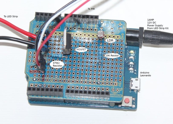
I built a second copy of the electrical circuit on an Arduino prototyping shield. This along with a second Arduino was installed near the approach to the top of the stairs. For now, the Arduino and senors simply sit on the floor up against the wall. Some double sided tape holds the PIR to a door frame. The PIR is facing down into the stair well and detects motion both at the top of the stairs and the bottom. The PIR connects to the Arduino prototyping shield via some jumper wires. The photo shows my finished rig with the two sets of cables leading to the PIR and the LED strip.
Source: Motion Activated Automatic LED Stair Lighting With Arduino