Summary of MKR1000 RGB Strip Controller
This article details the creation of a custom RGB LED strip controller using an Arduino MKR1000 and a TLC5940 driver. The project involves designing a PCB, writing a custom library for the ARM-based MKR1000 to handle PWM signals, assembling hardware including MOSFETs and power supplies, and developing a Windows Universal App for timeline-based lighting control. The author overcame challenges such as incorrect MOSFET logic, voltage drops on red channels, and connector issues to achieve a fully functional WiFi-enabled lighting system.
Parts used in the MKR1000 RGB Strip Controller:
- Arduino MKR1000
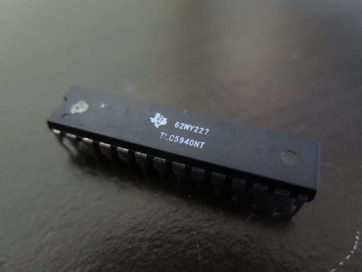
- Texas Instruments TLC5940
- 12V 30A Power Supply
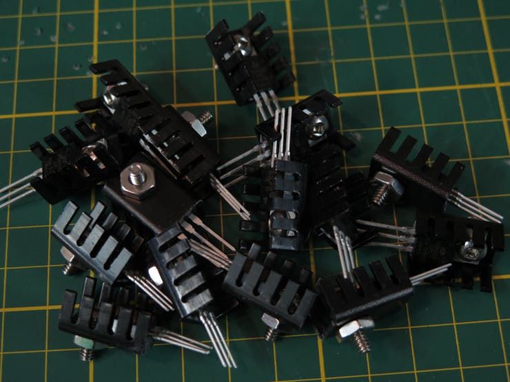
- MOSFETs
- 5V Regulator
- Resistors and Capacitors
- RGB LEDs (for status indicators)
- Solderless LED strip connectors
- Aluminium extrusions with diffusers
- Heatshrink tape
- JST connectors
- SparkFun shipping box
- 10mm fans
- Cable management clips
Using the power of a winning idea, an MKR1000, and a TLC5940 to add RGB lighting to my workspace.
Things used in this project
Hardware components |
||||||
 |
|
|||||
|
||||||
|
||||||
Software apps and online services |
||||||
 |
|
|||||
 |
|
|||||
Hand tools and fabrication machines |
||||||
 |
|
|||||
Story
Created for the World’s Largest Arduino Maker’s Contest
Back in December I started to design my first PCB, a board for driving 5 RGB LED strips to do some lighting around my desk. I had finished the main parts of it (or so I thought), and all I needed was to decide on a microcontroller. Then around comes the Arduino contest. I entered my idea for creating my controller and using it to add lighting to my desk, and it won the first phase.
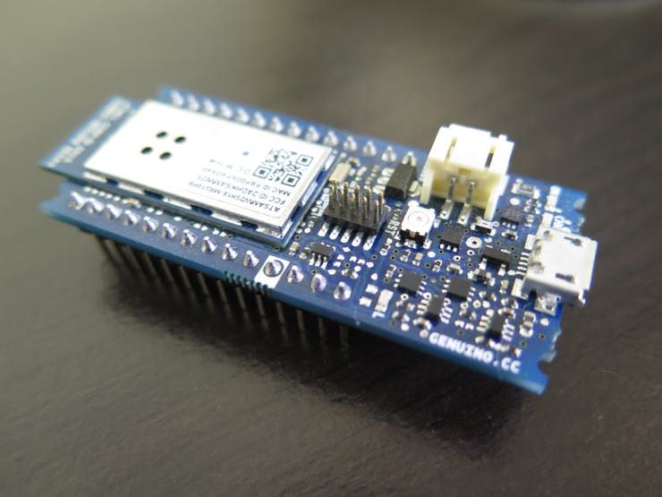
The MKR is the first Arduino WiFi board I’ve ever used, along with being my first PCB, and the biggest project I’ve ever done. It became quite the learning experience with all the issues, accidental short-circuits, and more.
Designing the PCB
Back when I first started putting together the schematic for my controller, I knew next to nothing about transistors, PCBs, LED Strips, and the TLC5940 I used to drive the whole thing.
After researching how MOSFETs work, I started looking into how to control LED strips with an Arduino, and came across the TLC5940 as being popular. I read about how to use it with an Arduino, read the datasheet, and decided to use it.
After deciding on those main details, I assembled the basics of the schematic – a 12v Power jack, 5V regulator for the TLC, the necessary resistors and capacitors for the TLC, and the MOSFETs. I also added RGB LEDs inline with the MOSFETs, which turned out later to be a mistake.
During Christmas, I put aside my plans for finishing and making the board, and the weeks following while I worked on some other projects. Then around came the Arduino contest and I decided this was a good chance to enter my idea for my controller, since if my idea won I would have an Arduino to use.
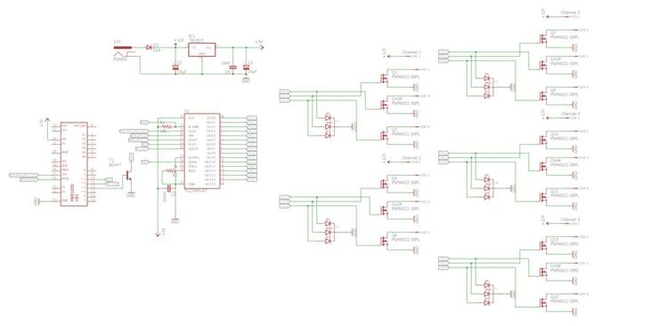
My idea won, and as soon as I got my MKR a week later I created an Eagle part for it, added it to my design, and sent the gerbers off to PCBWay for fabrication.
At the bottom of this project there is a download for the zip file with the Eagle files and gerbers. Here is the Digikey cart with all the parts I used.
Prototyping the Design
I probably should have prototyped the design before ordering the PCB and all the parts, but I didn’t have much time, so I ordered everything, got the parts first, and then prototyped the design on some breadboards.
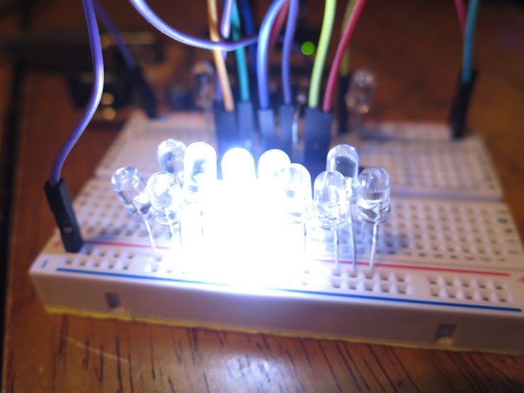
I grabbed my old Arduino Decimilla I had lying around, hooked it up to a TLC5940, and grabbed a library for the TLC from Github. In 5 minutes I had the TLC turning LEDs on and off, dimming them, and a little later I had it switching some of the MOSFETs.
After seeing how nicely everything played together on the breadboard, I was pretty confident about the PCB working like it should.
Writing a TLC5940 Library for the MKR
After seeing how well everything worked on the breadboard with the Decimilla, I switched the breadboard circuit over to using the MKR100, hooking everything up in the same way that the PCB was wired.
I went ahead and tried to flash the TLC test sketch I used on the Decimilla onto the MKR, and that’s when I realized that the MKR1000 was ARM based, not AVR based like the other Arduino boards, which meant that the existing libraries for the TLC wouldn’t compile for the MKR.
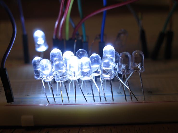
I spent about a week writing a library for use with the MKR1000, and a library for accessing the Control Timer Counters on the MKR so I could use them to fire the clock signals for the TLC in the same way other libraries did it, and in the end I had a couple of working libraries running the TLC off the MKR.
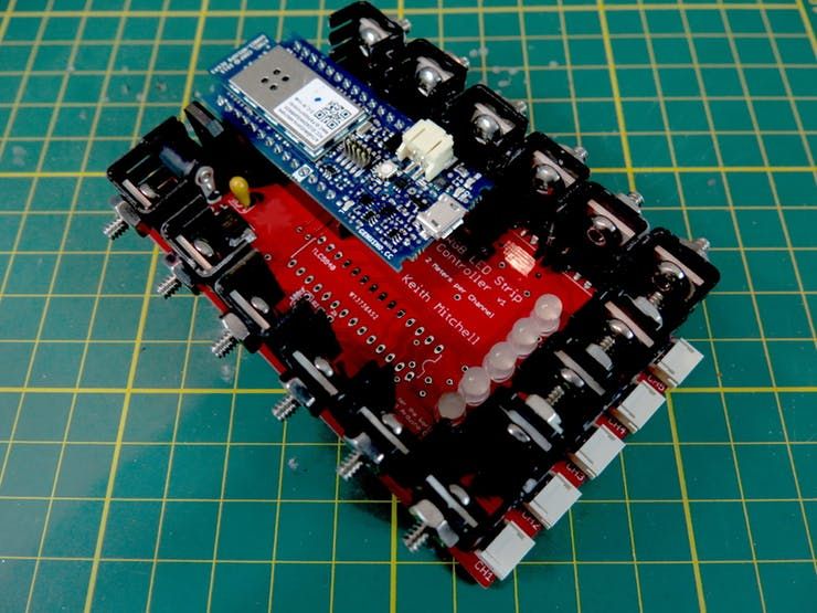
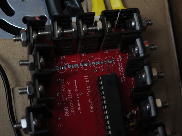
Assembling the Board
Once I received all the parts, the PCB, and some really small solder I ordered just for this project, I started assembling the board.
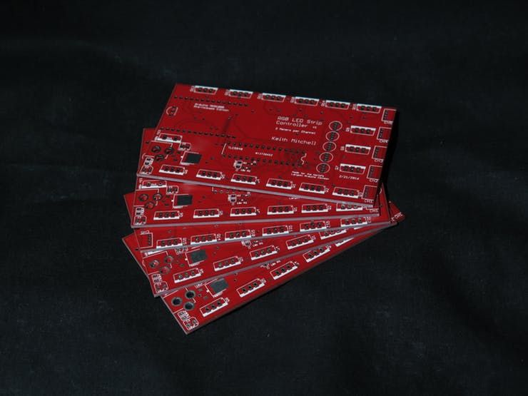
Several late nights, almost a whole roll of solder, and lot of probing with a multimeter later – I had everything but the TLC in place.
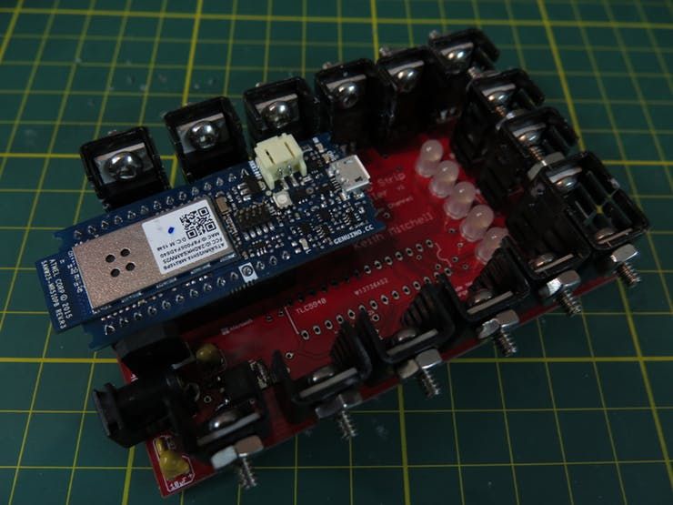
I had received the power supply by this time, so I hooked it up to the board, and put the MKR into the headers for it, and it worked! The 5V regulator, also my first SMD hand-soldered part, was working perfectly and powering the MKR1000 off the 12v input.
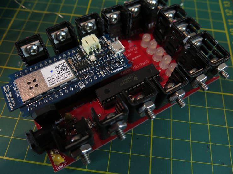
I soldered in a DIP socket for the TLC (if it burned out, I wanted to replace it easily!) and plugged one of the TLC5940s into the socket, and powered the board without the MKR in to make sure that everything was working, and here is where I started finding issues.
After a bit of probing with the multimeter, I could tell that the TLC was powered and working. I plugged in the MKR, which was flashed with a sketch for controlling the TLC, and nothing lit up. Uh oh!
The 5 RGB status LEDs just stayed blank, they wen’t showing any colors like they were supposed to. I probed the outputs and found that no power was passing through the outputs on the TLC.
Fixing my Mistakes
After probing the TLC for a bit, and reading the datasheet for it again, I realized my first mistake.
The TLC is designed to sink the outputs to ground, but the way I used it with N-Channel MOSFETs meant that I had expected it to supply voltage instead of sinking to ground.
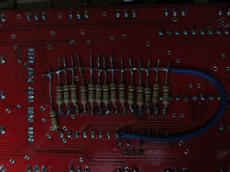
Luckily. I found that I could just add 10k pullup resistors to all the outputs on the TLC and it would almost work like it was supposed to. One side effect of this is that I can’t turn the MOSFETs fully off, they’re always slightly on. I’m not sure why that is, but I think the 10k pullups may have created a voltage divider with the 2k current limiting resistor, which means that the max voltage is then 4.167v.
The other side effect of my design mistake is that I had to reverse the “on” and “off” values for the TLC, meaning that the value of 4059 for full on becomes 0 and vice-versa.
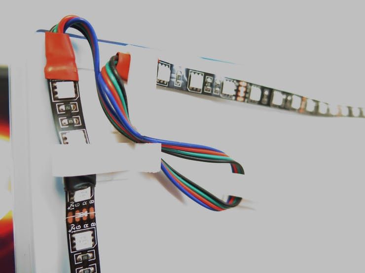
Preparing the LED Strips
The LED strips took a couple days to assemble. I had ordered some solderless LED strip connectors 3 months previously from Amazon, but hadn’t received them yet, so I needed to solder the wires onto the LED strips.
The first challenge was doing the wires for the strips that go under my desk. For those, I had bought some aluminium extrusions with diffusers to help diffuse the light and make it less harsh.
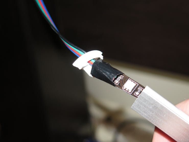
To do the wires for the strips that would be in the extrusions, I cut a piece of LED strip that matched the length of the extrusion, and then soldered the wires on folded back, wrapped some tape and heatshrink around the connection, and then folded it the right way and wrapped a bit more tape around it, finishing it off with the end cap.
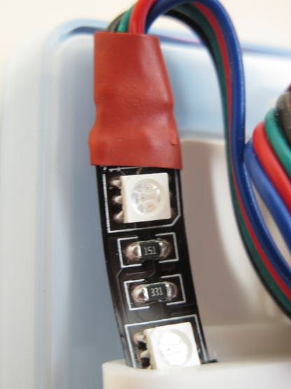
The strips for the monitors and the back of the desk were pretty straight forward. I just needed to solder them on the usual way, and then seal them off with some heatshrink.
Adding the crimps and male JST connectors to the wires was a nightmare. I hadn’t used crimps before, and when I ordered them I thought they were larger than they really were. Despite that they would have worked fine if they hadn’t been so tiny, and if the wire hadn’t been slightly too large.
It took me 2 nights (about 8 hours in all) to attach 20 crimps with a bit of solder, needle-nose pliers, and a slightly-too-large crimping tool I got from the hardware store.
After this I decided I was never going to use micro-crimps again.
Making an Enclosure
Before I got everything else set up, I wanted to make some sort of enclosure that I could stick under my desk to keep it all out of the way.
My Dad jokingly made a comment about using a cardboard box, which I actually ended up doing. I had a SparkFun shipping box that just happened to be the right size to fit the power supply and PCB.
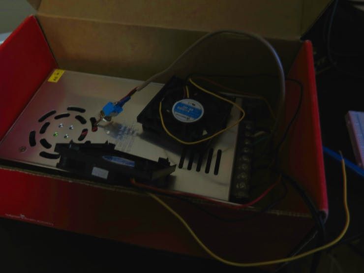
I also went out and bought a couple of 10mm fans from the local surplus store to use for cooling. I soldered them to a switch and connected to another terminal on the power supply. Without the fans the reverse voltage protection diode gets pretty hot when all the strips are running.
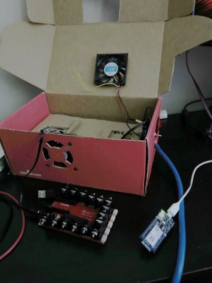
I cut holes for the switches, the fans, the wires for the LED strips, and the power cord, then fitted everything into place.
To insulate the PCB from the power supply so the board didn’t short-circuit, I just used another piece of cardboard taped to the top of the power supply.
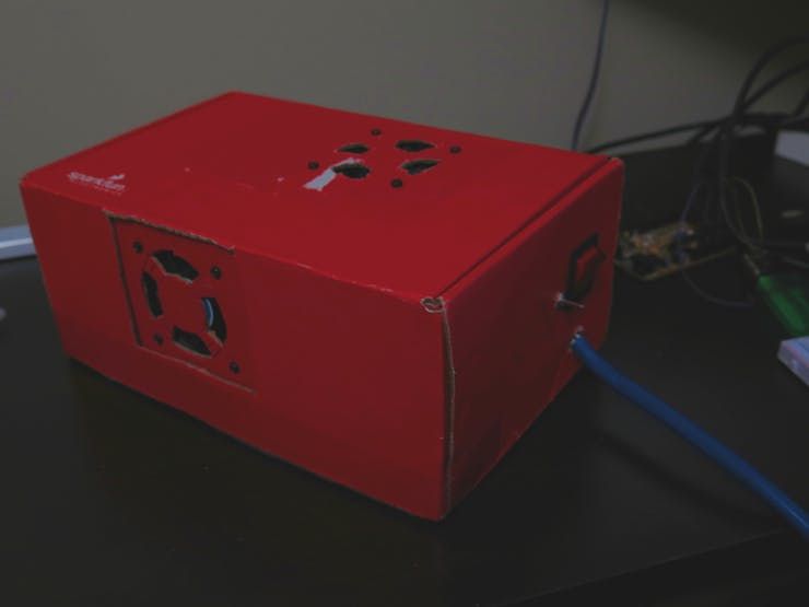
The final step was adding a power switch for the PCB (I spliced a large, dangerous looking 120V switch I had into the 12v line for the the PCB), and making sure it all worked.
Mounting the Strips
The only spot where the adhesive on the back of the strips actually worked was along the back of my desk. The adhesive didn’t work on the monitors, it just kept peeling back off.
I used some cable management clips to mount the strips on the back of the monitor by cinching them tight, and then using double sided tape to attach them. That worked well. It held them in place and kept them out of the way.
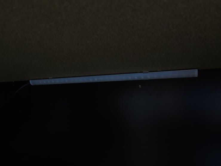
To attach the diffusers under the desk, I used double sided mounting tape on the brackets that came with them. I was unable to find screws that had a head that actually fit the countersink in the mounting brackets.
Finally, I ran all the wires from the strips around the back of the desk to box with the control board and power supply, and plugged it all in.
First Run and the Issues it Revealed
After connecting everything and running some sketches on the MKR, I noticed that one issue still persisted that I had thought was just a one-time issue with the code. All the red channels were super dim, so dim that they wouldn’t reflect off the wall behind the desk. The red and green channels were fine, though.
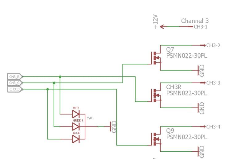
After thinking through it and looking at the schematic, the only difference I could possibly think of was the lower voltage draw from the R LED in the RGB status LEDs on the board.
I carefully de-soldered one of the LEDs, and sure enough the red channel started working and the green and blue channels were brighter. I decided to de-solder the rest of the status LEDs.
I honestly don’t understand what happened there. I’m guessing it had something to do with the R LED having a lower voltage draw than the G and B LEDs, but I’m not sure how it could cause an issue like that.
Creating the Arduino Sketch
The sketch that runs on the MKR is pretty simple. Using the TLC library I wrote for the MKR, it initializes the TLC, connects to the wifi, and then listens for post requests to the board.
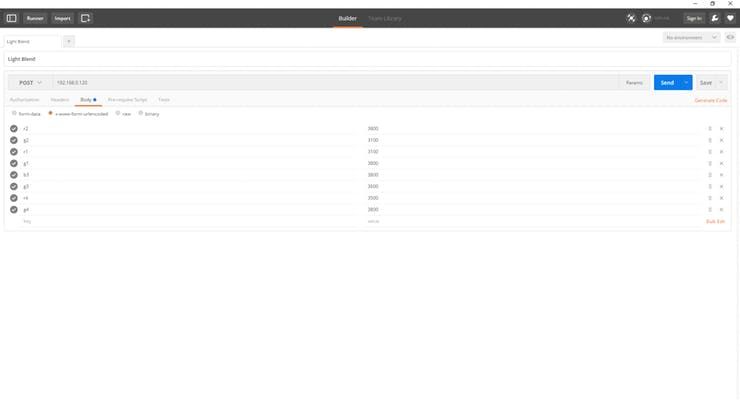
If there is a post request it parses the “x-www-form-urlencoded” html data that was posted to it, and if the key matches certain conditions then it sets the respective colors on the channel for the key.
Example: “r1=4059” A key of r1 tells the Arduino to set the r color of the first channel on the board to 4059.
Creating the Universal Windows App
I had started working on an app while waiting to receive the parts and PCB, but unfortunately my external hard-drive decided to fail when I was ready to finish it. I hadn’t done any backups since I started writing it, so I lost the whole project.
With only 3 days left until the contest deadline, I started work on another app.
Since I had so little time, I decided to go with making a simple app for the contest and expand on it later for my personal use.
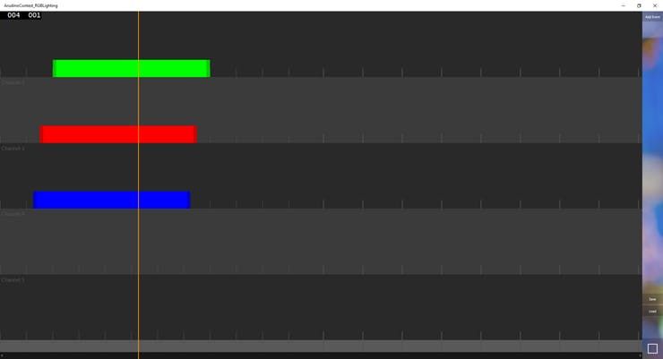
With that in mind, I decided to create a “timeline” that you add color events to, and then “play” it back on the LED strips.
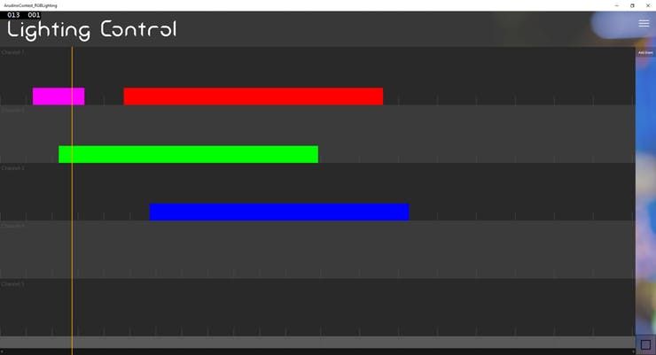
I created a basic app in one day, where you could press a button to add events to the timeline, and then click on then and change options like the channel, colors, and start and end position.
I also made the whole timeline scalable, so by changing a variable for the length of the entire timeline in seconds in the code before launching the app, I could make the timeline bigger or smaller.
I spent the next day day adding improvements like being able to drag the events around to re-order them, and being able to grab and move the start and end positions of the clips, as well as improving how the events are sent to the MKR by setting a “second resolution”.
The resolution works by taking an integer that tells the script how many times a second events can be called. By default it’s set to 4, which means that events can be called every (1000/4) milliseconds, meaning an event is fired every .25, .5, and .75th of a seconds. This makes it so that a post request is only sent to the MKR every 4th of a second instead of every time a loop happens, which tends to overwhelm the MKR.
I used C#’s extremely simple XML serialization to add a save and load feature, so that I could easily save and load timeline events.
Seeing it Work
Now that all the code is written and the electronics are assembled, we can start using the program to create some cool lighting effects with the controller.
By hitting the “Add Event” button in the upper-right we can add another event to the timeline. Right-clicking the event opens up the options flyout where we can change the channel, color, and the start and end times. By hitting play the timeline is converted to arrays that hold the colors for each frame, which are then sent to the MKR.
Since the Arduino is just hosting a webserver that responds to post requests, I’m also able to use a tool like Postman to change the colors if I want to.
Or of course I can just use plain old Arduino Sketches to control the whole thing, like I do here with an hsv color wheel.
Wrapping Up
This project was a great learning experience. I learned how to use MOSFETs, how to look into the source code for Arduino bootloaders to use advanced system functions, and how to access an Arduino’s registers.
Some things I would do differently if I re-did this board are:
- fixing the way I control the MOSFETs using the TLC to actually work without adding pullup resistors
- either remove or change the circuit for the RGB status LEDs
- use a different type of connector for the LED strips, maybe just some good ol’ headers
- add some kind of connector or some headers so I can access the pins that aren’t used by the TLC
- add some kind of a fan control. The fans work great for keeping it cool, but if they could change speed based on how much power the board is drawing they could run quieter and more efficiently
Schematics
Code
Source : MKR1000 RGB Strip Controller
- Why did the existing TLC libraries fail on the MKR1000?
The MKR1000 is ARM based, whereas the existing libraries were designed for AVR based Arduino boards. - How did the author fix the issue where the TLC could not turn off the MOSFETs?
The author added 10k pullup resistors to all outputs on the TLC to compensate for the sinking output design. - What caused the red channels to be super dim during the first run?
The lower voltage draw from the red status LEDs on the board was causing the issue until they were de-soldered. - How does the app control the resolution of events sent to the MKR?
The resolution is set by an integer that determines how many times per second events can be called to prevent overwhelming the MKR. - What material was used to create the enclosure for the project?
A SparkFun shipping cardboard box was used to house the power supply and PCB. - How were the LED strips mounted on the monitors since adhesive failed?
The author used cable management clips cinched tight and double sided tape to attach them. - What software was used to write the library for the MKR1000?
Microsoft Visual Studio 2015 was used to create the custom library and the Windows Universal App. - How is the power supply cooled when running all strips?
Two 10mm fans are soldered to a switch and connected to the power supply to cool the reverse voltage protection diode.