Summary of Memsic 2125 Accelerometer using Arduino
This article explains how to interface a Memsic 2125 two-axis accelerometer with an Arduino. The sensor outputs pulse-width modulated signals representing acceleration in X and Y directions, which the Arduino measures using the `pulseIn()` function to calculate values in milli-g's. The project requires basic wiring between the sensor and the microcontroller to read data via serial communication.
Parts used in the Memsic 2125 Accelerometer Project:
- Arduino Board
- Memsic 2125 Accelerometer
- Breadboard
- Hook-up wire
The Memsic 2125 (datasheet) is a two-axis accelerometer capable of measuring acceleration up to plus or minus 2g. It has a simple digital interface: two pins (one for each axis) emit pulses whose duration corresponds to the acceleration of that axis. By measuring the length of that pulse, in microseconds, using the Arduino’s pulseIn() function, it is possible to determine the rate of acceleration and to use that data for your purposes.
Circuit
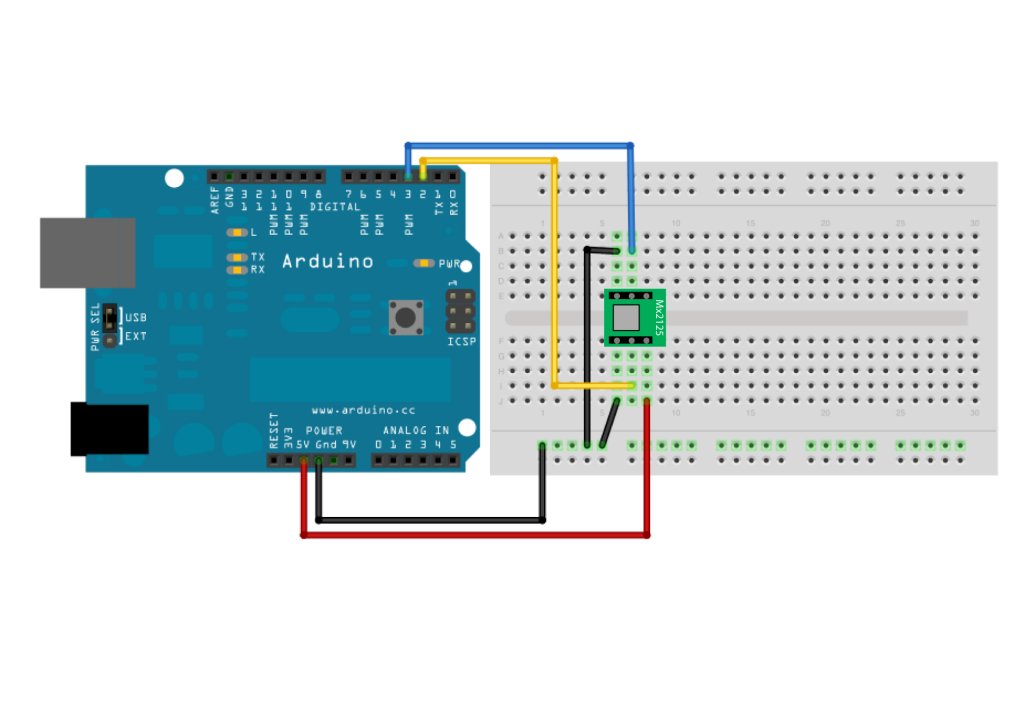
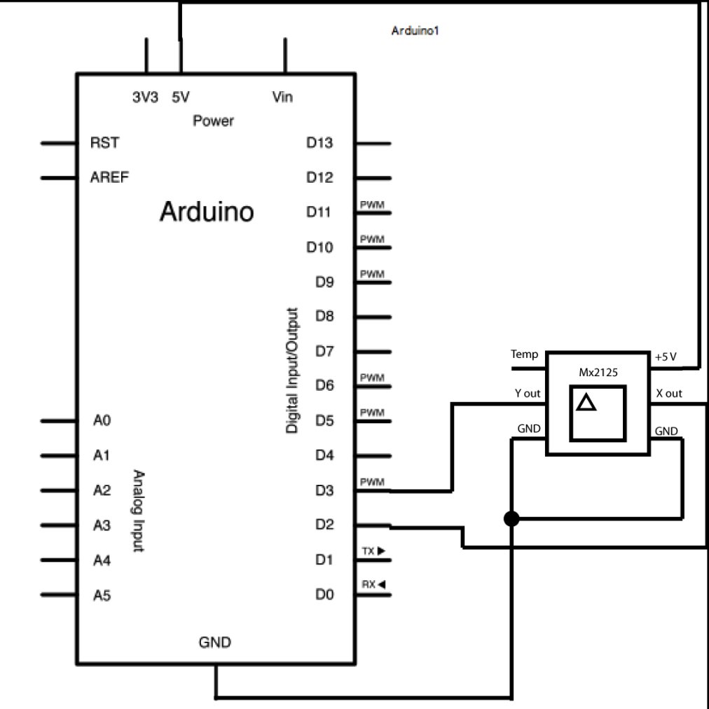
Use the small triangle on the Memsic to properly orient the sensor on your breadboard. Connect the 5V and GND pins of the Memsic 2125 to the power and ground ports on the Arduino. Connect digital pin 2 of the Arduino to the X out pin of the accelerometer, and digital pin 3 to the Y out pin.
Your Arduino must be connected to your computer in order for it to transmit serial data.
image developed using Fritzing. For more circuit examples, see the Fritzing project page
Schematic:
Code
/*
Memsic2125

Read the Memsic 2125 two-axis accelerometer.  Converts the
pulses output by the 2125 into milli-g's (1/1000 of earth's
gravity) and prints them over the serial connection to the
computer.

The circuit:
* X output of accelerometer to digital pin 2
* Y output of accelerometer to digital pin 3
* +V of accelerometer to +5V
* GND of accelerometer to ground

http://www.arduino.cc/en/Tutorial/Memsic2125

created 6 Nov 2008
by David A. Mellis
modified 30 Aug 2011
by Tom Igoe

This example code is in the public domain.

*/
Hardware Required
- Arduino Board
- (1) Memsic 2125 Accelerometer
- bread board
- hook-up wire
For more detail: Memsic 2125 Accelerometer using Arduino
- What is the measurement range of the Memsic 2125?
The sensor is capable of measuring acceleration up to plus or minus 2g. - How does the Memsic 2125 output data?
It uses a digital interface where two pins emit pulses whose duration corresponds to the acceleration of each axis. - Which Arduino function is used to measure the sensor pulses?
The pulseIn() function is used to measure the length of the pulses in microseconds. - How should the Memsic 2125 be oriented on a breadboard?
Use the small triangle on the sensor to properly orient it. - Which Arduino pins connect to the X and Y outputs?
Digital pin 2 connects to the X out pin and digital pin 3 connects to the Y out pin. - What units are the acceleration values converted to in the code?
The code converts the pulses into milli-gs, which is 1/1000 of earth's gravity. - Why must the Arduino be connected to a computer?
The connection is required for the Arduino to transmit serial data to the computer. - How many pins does the Memsic 2125 use for its simple digital interface?
It uses two pins, one for each axis, to emit pulses.