Greetings everyone!
We hope you are in good health.
We live in a world where any form of physical contact between two human beings is starting to pose serious health issues. Keeping this in mind, a while ago, we had worked on an automatic water tap using an Infrared sensor to detect the presence of a human hand, a solenoid valve to control the flow of water through the tap, and finally, an Arduino ProMini to serve as the brains of the system.
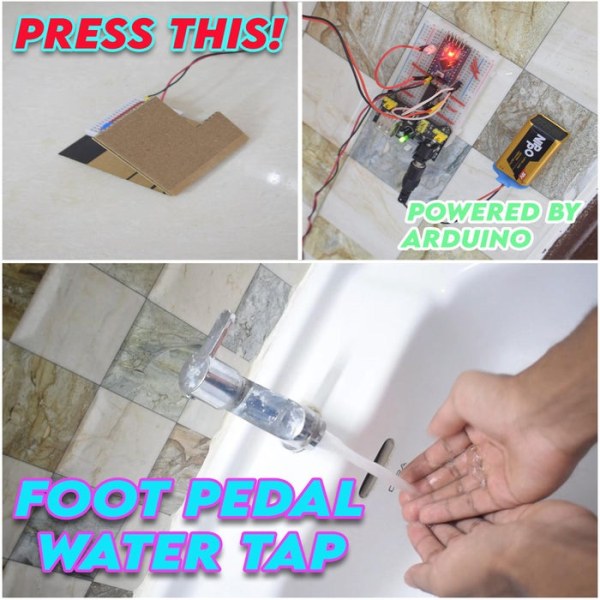
In this Instructable, we will guide you through the process of controlling the flow of water through your water faucet with the help of a foot pedal.
We will still employ the trusty Arduino ProMini as the brains of the project and use a tactile pushbutton as the substitute for the IR sensor.
The principle of operation is really simple, a pushbutton sends a signal to the Arduino when the foot pedal is pressed and the solenoid valve opens along with the status indicator LED going off. Upon taking releasing the foot pedal, the water stops flowing from the tap.
DISCLAIMER: WE WASTED NO WATER IN THE TESTING OF THIS PROJECT AND RESPONSIBLY REUSED IT.
Step 1: The Prerequisites
A) SOFTWARE:
a) Arduino IDE: Download here.
b) FTDI drivers: Download here.
B) ELECTRONICS:
a) Square tactile pushbutton with cap: Buy here.
b) Arduino ProMini: Buy here.
c) FT232RL: Buy here.
d) USB type A to mini B cable: Buy here.
e) 3.6-6V DC bistable solenoid valve(1/2 inch): Buy here.
f) L293D motor driver IC: Buy here.
g) 5V White LEDs: Buy here.
h) 9V battery: Buy here.
i) 9V cell clip connectors: Buy here.
j) 5.5mm DC barrel plugs: Buy here.
k) Half-sized breadboard: Buy here.
l) Mini breadboard: Buy here.
m) HW-131 breadboard power supply module: Buy here.
n) Dupont jumper wires: Buy here.
o) Multi-strand wires: Buy here.
p) Male berg strips: Buy here.
C) TOOLS:
a) Soldering station: Buy here.
b) X-Acto knife: Buy here.
c) Scissors: Buy here.
d) Adjustable wrench: Buy here.
D) MISCELLANEOUS:
a) Corrugated cardboard: Buy here.
b) 1/2 inch elbow threaded coupler(female): Buy here.
c) Teflon tape: Buy here.
d) 3M Scotch packing tape: Buy here.
e) 3M Scotch heavy-duty double-sided tape: Buy here.
f) 3mm yellow heat shrink: Buy here.
Step 2: Let’s Get Familiar With the Main Components
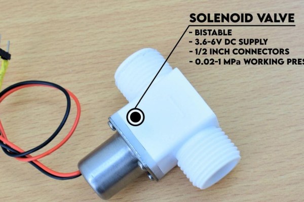
1) The solenoid valve:
A solenoid valve is an electromechanical device used to control the flow of a fluid through it by energizing an electromagnet which in turn moves the plunger to either restrict or allow the flow of fluid through the valve.
A bi-stable solenoid valve has the ability to “remember” its state even after the power/signal is cut off. For example, a bi-stable solenoid valve will remain closed after receiving a positive/negative pulse depending on the construction, even after the signal is no longer sent. This helps in keeping the power consumption and the temperature rise of the coil to the very minimum.
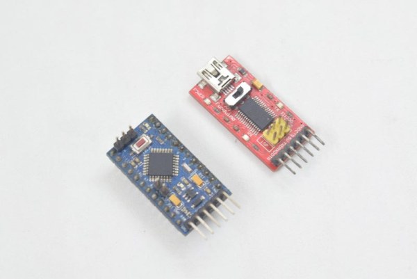
2) The Arduino ProMini:
Our goal is to read the value from a tactile pushbutton and use it to open and close the solenoid valve. We can do this by using an I/O pin on the Arduino to read the digital state of the button and use this to control the input values of the motor driver IC, which in turn will control the solenoid valve. An LED can also be programmed to light up when the foot pedal is pressed and the water starts to flow out of the tap.
3) The L293D MOTOR DRIVER IC:
An individual I/O pin on an Arduino ProMini can supply a maximum current of 40 milliAmperes. The solenoid valve under test draws approximately 500 milliAmperes during its operation, so we will use an L293D motor driver IC which can supply up to 1.2 Amperes peak and 600 milliAmperes continuously. The IC can operate off an Arduino Pro Mini’s 5V output and can be used to control a load of up to 36V!
Step 3: Let’s Prepare the Foot Pedal | Part 1:
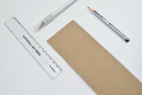
Alright, now gather these ingredients and let’s get over the input part of the system.
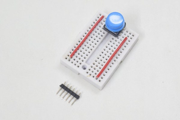
A sheet of cardboard, a mini breadboard, a tactile pushbutton with a cap, some single-core and multi-strand wires, male header pins and heat shrink tubing, double-sided and packing tape.
1) Start by marking out the lines for cuts and creases.
2) Make a hinge with the help of packing tape.
Step 4: Let’s Prepare the Foot Pedal | Part 2:
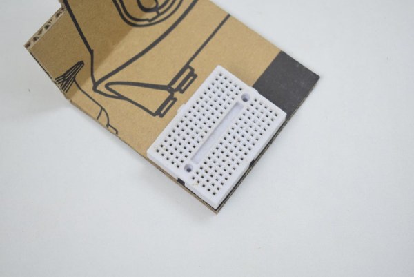
1) Adhere the mini breadboard to a corner of the foot pedal’s base with the help of double-sided tape.
2) Install the pushbutton on the breadboard and use hookup wires to extend the terminals to the extreme end of the breadboard.
Step 5: Let’s Prepare the Foot Pedal | Part 3:
1) Remove the 2 pins on the middle of a 6 pin berg strip.
2) Solder up multi-strand wires to the remaining pins on either side.
3) Solder the other end of the wires to a 2 pin berg strip to finish up the foot pedal’s extension cable.
4) Connect the 4 pin berg strip to the pushbutton.
Use heat shrink tubing wherever necessary.
Step 6: Let’s Prepare the Control Unit | Part 1:
Now that were’s done with the input side of the circuit, let’s move on to the processing side.
Gather these ingredients and let’s get started!
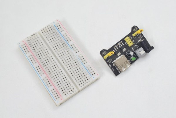
An Arduino ProMini, a half-sized breadboard, a breadboard power supply module, an L293D motor driver IC and some single-core wires.
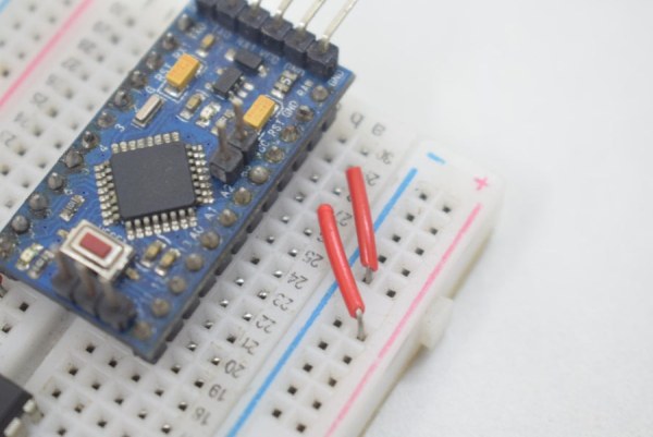
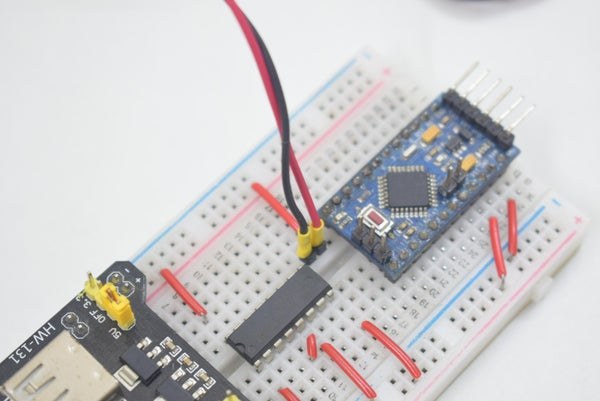
1) Install the Arduino ProMini and the breadboard power supply module to the extreme ends of the half-sized breadboard. Ensure that the power supply module is set to provide an output of 5 Volts.
2) Install the L293D IC between the Arduino and the power supply module.
Step 7: Let’s Prepare the Control Unit | Part 2:
1) Connect the Arduino’s VCC and GND pins to the breadboard’s +ve and -ve rails respectively.
2) Connect the L293D’s EnableA, VChip and VExternal to the +ve rail of the breadboard. Also, connect the GND pins of the IC to the -ve rail.
3) Use a hookup wire to connect the +ve rail to an empty row on the breadboard and connect a jumper wire from digital pin 3 to the next empty row. This will serve as our switch’s port.
Step 8: Let’s Prepare the Control Unit | Part 3:
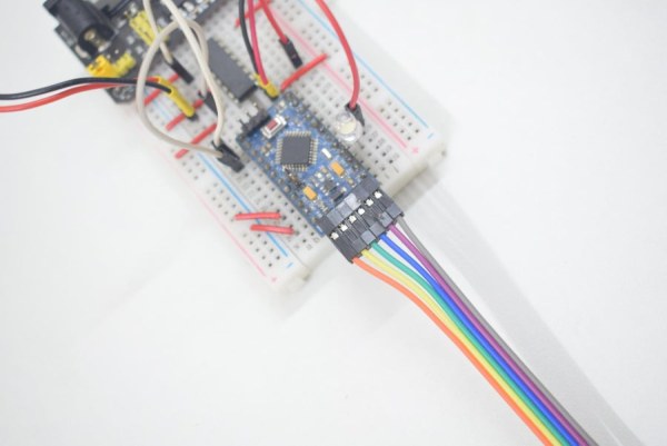
1) Connect the foot pedal’s cable to the breadboard.
2) Connect the pushbutton’s terminal to digital pin 3 on the Arduino.
Step 9: Let’s Prepare the Solenoid Valve and Status Indicator LED
Now that we are done with the control unit, let’s move on to the output stage of the system.
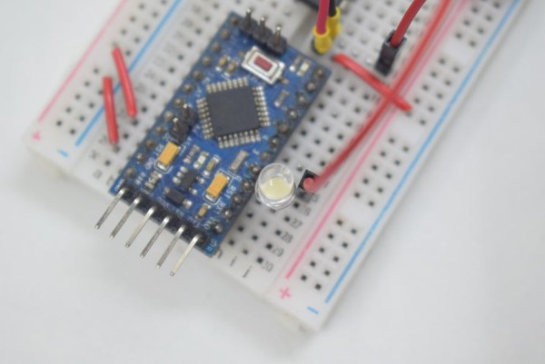
Pull out a DC solenoid valve and a 5V LED from your inventory and make the following connections:
1) LED’s positive terminal to digital pin 2 on the Arduino and negative terminal to GND.
2) Solenoid valve’s terminal A to output A1 on the IC and terminal B to output A2.
3) Use jumper wires to connect digital pins 10 and 11 to the IC’s InputA1 and InputA2 respectively.
Step 10: Final Breadboard Schematic
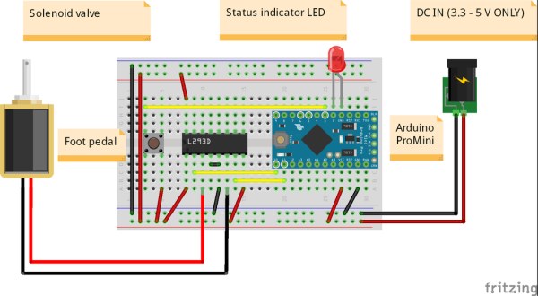
Pushbutton’s terminal A -> GND
Pushbutton’s terminal B -> Digital pin 3 on the Arduino
L293D’s pin 1,8, and 16 -> Arduino’s VCC
L293D’s pin 2 -> Digital pin 10 on the Arduino
L293D’s pin 7 -> Digital pin 11 on the Arduino
L293D’s pin 4 and 5 -> GND
STATUS INDICATOR LED’S POSITIVE TERMINAL -> Digital pin 2 on the Arduino
STATUS INDICATOR LED’s NEGATIVE TERMINAL -> GND on the Arduino
SOLENOID VALVE’S TERMINAL “A” -> PIN 4 on the IC
SOLENOID VALVE’S TERMINAL “B” -> PIN 6 on the IC
Step 11: The One With the Programming
Now let’s move on to the software side of the system.
1) Please find the attached, and download it.
2) Open it using the Arduino IDE and verify the same.
3) Select your communication port and board.
4) Upload the code.
Source: FOOT PEDAL ACTIVATED WATER TAP