Hi,
In this instructable I’m going to teach you how I made my own “Jibo” but called “Twinky”
I want to clear this up… THIS IS NOT A COPY! I WAS BUILDING TWINKY AND THEN I REALIZED THAT SOMETHING LIKE THIS ALREADY EXIST :c
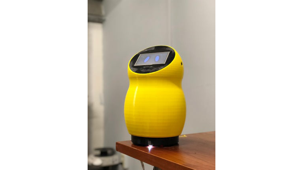
It has almost the same functions but It doesnt need an internet connection and oviuousley it doesnt need a server. (Of course this make a lot of limitations,comparing with the functions of the Jibo Robot)
IT CAN SPEAK! PLAY MUSIC, SET TIMERS, ALARMS, TURN ON/OFF THE LIGHTS OR OTHER APPLIENCES, IT HAS A CALCULATOR AND A WEATHER STATION! DATE & TIME, BLUETOOTH 4.0, EVERYTHING WITH VOICE COMMANDS!!!! and also with a touch screen, it has one little motor so it can turn arround when one of the two microphones hear you talk or make a noise.
You can record your own commands in any language, I’m in México so everything is in spanish.
The “brain” is an Arduino Mega, where all the code is running, there is a different board for the voice recognition called “SpeakUp Click” from “Mikroelektronika” I’ll leave all the links later so you can purchase this different boards.
Step 1: Design & 3D Printing // Documents

I want it to make it “cute” and friendly so I decided to call it Twinky and the best color I found was yellow, also it was the only nice color I have arround.
Everything was made in SolidWorks and then 3D printeded in a Rise N2 Plus.
The body is actually pretty big, arround 32cm tall and 19cm wide.
Here you have all the STL files.
The components are…
-HEAD
-FACE
-BODY
-BASE
-SPEAKER ENCLOSURE
-BREARING ADAPTOR
-GEARS
https://drive.google.com/open?id=1GApWHVjIjuwkE-Vm…
In this link is everything, from the audio notes that you should place inside the SD memory card, an .spk file thet are the voice commands, the music, the STL files, the Arduino Code, everything!
Step 2: Components
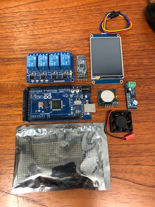
For the functions I put it in there are a lot of modules that are inside twinky.
Arduino Mega
SpeakUp Click
RCT
Bluetooth
4 Rellay Module
Audio Amplifier
Speaker
DC Motor
2 Digital Signal Microphones
4.3in ITEAD touch screen
SD Module
RGB LED
Arduino Mega Prototyping shield
And so on … other components like some resistors, cables and others I wont show every single detail in this instructable, It would make it sooooo long … but if you have any questions I’ll be happy to answer! And explain you every small detail.
https://www.itead.cc/nextion-nx4827t043.html.
https://www.dfrobot.com/product-60.html
https://www.mikroe.com/speakup-click
Step 3: Schematic

This is simple shcematic, everithing is represented by a connector, from de Arduino Mega to every module, with the label you can see which module is.
The bluetooth is connected to de Serial1, the ITEAD Screen in the Serial2, as you can see there are still plenty of unused pins.
The temperature module is connected at pin 13.
The RTC is connected to SDA and SCL (Pin 20,21)
The SD Card reader is define to be connected in Pin, 50, 51, 52 & 53.
SpeakUp board is powered by 3V3 and all the other modules are 5V
I didn’t place the L239D motor controller but it is really simple to use DO NOT CONNECT THE MOTOR DIRECTLY TO THE ARDUINO.
Also… the ONLY functional speaker output is at pin 46.
Step 4: Arduino Mega Shield
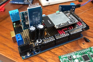
I put all the components in the place I found better, under the SD module there is a L239D motor controller.
Solder everything together to VCC, GND and the connections with the pins I place in the Arduino program, you can change all the pin deffinitions if you want to, and then make the connections as you want too… you dont even need the shield haha, it will work with cables too but is messier.
You should connect all the components individually, I mean one by one and test it and then in the code you can “put it all together” for example:
If you want to connect the RTC then search on internet how to connect an RTC to Arduino Mega and make the connectios, test it and then go to the next modue.
Again… I’m sorry if I dont expliain all of this in the instructable but that would be too much work, and it will be an infinite instructable.
I made a small 12V and 5V regulator and bought an audio amplifier, reeeealy simple.
IF SOMETHING IS NOT WORKING THEN WRITE ME A COMMENT AND I’LL BE HAPPY TO ANSWER! C:
Step 5: Put It Together
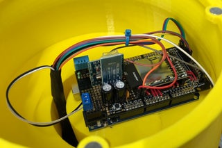
Twinkys brain will be inside him, with the audio amplifier and the SpeakUp click.
In the third picture you can se the microphones in the head
The motor, reallys, RGB LED and the speaker are in the base and connected with the brain trough the hole in the body
With the motor the body can turn if any sound activate one of the microphones, the rellays can be activate to control your appliences and the RGB LED shows the status of the program:
If there is an alarm running it will be pink, if you say “twinky” and detects you, it will be blue, and so on with the different commands.
Step 6: Face & Menu
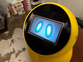
For the face I’m usign a Resistive touch screen form ITEAD, it is really simple to use, it can be controlled with serial communication! So it only takes 2 pins of the arduino!
You can send the value of any variabele in the screen, or when you press any button the ID is sent to the Arduino.
To make the face program ITEAD has an edditor
https://www.itead.cc/display/nextion.html
Is really simple to use but if you use a screen like me, the HMI program and the .tft will be on the Google Drive Link
The .tft is the documment you place in the SD card so you can charge the program to the screen.
There are a lot of videos on youtube that explain how to use the software.
Source: Meet Twinky the Cutest Arduino Robot
