One of our technicians recently asked for help determining the value of an SMT inductor. It was unmarked, and was many turns of very fine wire on a ferrite core. The resistance measured 26Ω, which for some reason gave our ancient LCR bridge a conniption, and read 30mH along with a blinking error message. The tech rightfully felt that such a small inductor could not possibly be 30mH.
I didn’t have another bridge, but I assured the tech there are other ways to do the measurement. One way is to solder a known capacitor in parallel with the unknown inductor to form an LC tank, preferably using a capacitor with 5 percent or better tolerance and an RF-quality dielectric such as C0G (NP0). One can then measure the resulting resonant frequency and calculate the inductance from that. To measure the resonant frequency one could build an oscillator around the tank, but it’s easier and faster to do the following with a standard function generator and some clip leads:
The function generator provides a voltage step in the form of a digital logic edge, preferably a fast risetime such as obtained from the function generator’s “sync” output. If a function generator is not available, a quickie oscillating edge generator can be breadboarded using any number of Schmitt inverting logic gates such as the 74xx14 as shown below:
The faster the logic family risetime, the stronger the excitation of the LC tank. The actual time between edges should be long enough to allow time for the tank transient to settle, but if using an analog scope the edge frequency should be high enough to get a reasonable repetitive CRT brightness.
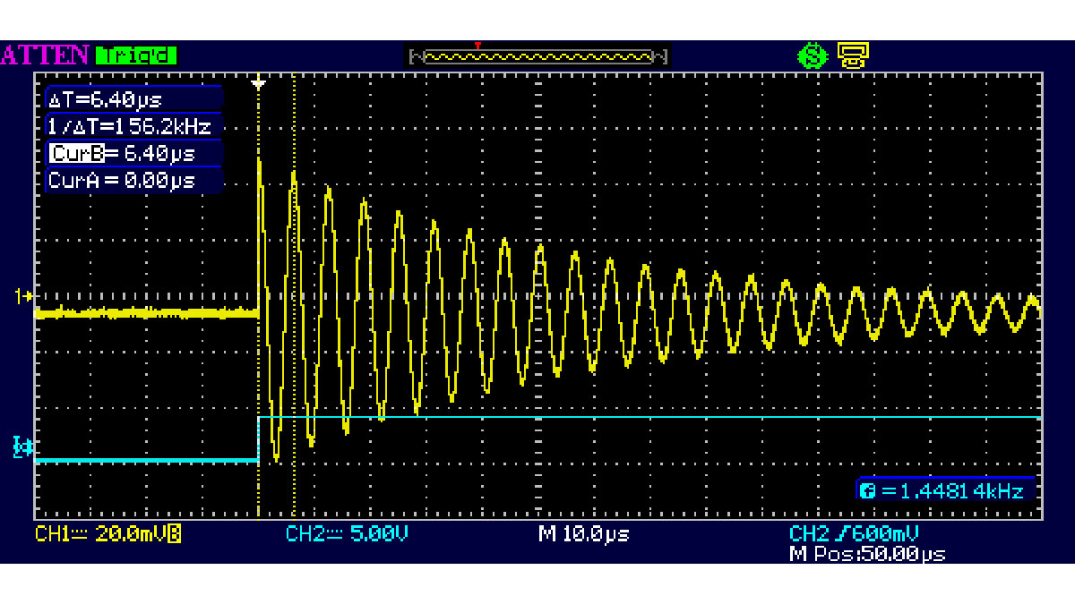
The resulting scope display looks like this:
The blue is the logic edge trigger, the yellow is the LC tank response. The digital edge through the 10pF capacitor twangs the tank in much the same way as a pick twangs a guitar string. The tank rings, and the resonant frequency can be measured with the cursors. It may be necessary to experiment with the value of the 10pF coupling capacitor to get a reasonable ringing amplitude, but its value should be kept much smaller than the capacitor paralleled across the inductor.
In this case the capacitor in parallel with the inductor is 1nF and the resulting frequency is 156kHz. From the resonance equation f = 1 / [2π(LC)0.5], the inductor calculates to be 1mH. This technique can be used to measure inductance down to the nanohenry region — the known parallel capacitor might need to be increased accordingly to maintain a reasonable ring frequency within the scope’s bandwidth.
Read more: Measure small LCs with a scope