A Dot-Matrix Display is a display device which contains light emitting diodes aligned in the form of matrix.This Dot matrix displays are used in applications where Symbol, Graphic, Characters, Alphabets, Numerals are need to be displayed together in static as well as Scrolling motion.Dot Matrix Display is manufactured in various dimensions like 5×7,8×8,16×8,128×16, 128×32 and 128×64 where the numbers represent LED’s in rows and columns, Also these displays comes in different colors such as Red, Green, Yellow, Blue, Orange, White.
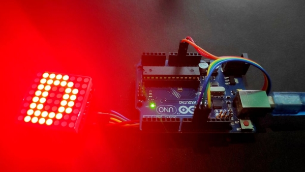
In this Instructable, I will be going through interfacing an 8×8 Dot Matrix which has a MAX7219 driver to an Arduino Uno.Let’s get started.
Supplies:
MAX7219
Step 1: Check the Package
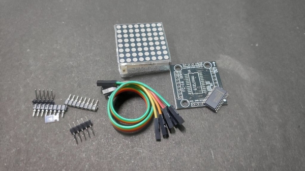
As you can see I have a smt version of the driver board ,it’s very important to verify each and every components needed as the smd components are very small in size and you can easily lose them.There are also dip version availabe online but I used the smt version for its size.
Step 2: A Little About This Particular Dot Matrix
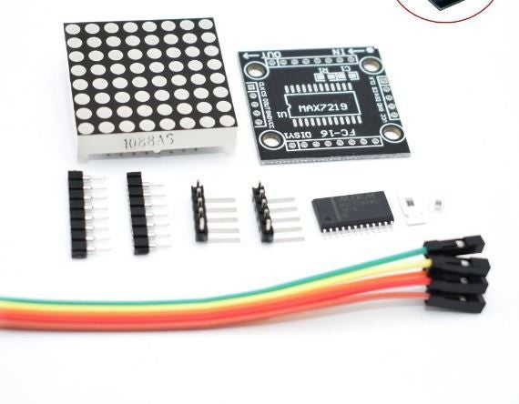
single module can drive the an 8×8 dot matrix common cathode.
Operating voltage: 5 v
Dimensions: length 3.2 cm X 3.2 cm wide X 1.3 cm high , holes with four screws, the diameter of 3 mm
Modules with input and output interfaces, support for cascading multiple modules.
Data IN and OUT terminals are specified on the module.
Step 3: The MAX7219 Driver
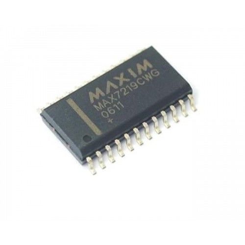
The MAX7219 is an IC designed to control a 8×8 LED MATRIX. The IC is serial input common-cathode (Common Negative) display drivers that interface microprocessors (or microcontroller) to 7-segment numeric LED displays of up to 8 digits, bar-graph displays, or 64 individual LEDs.
Features and Specifications
Operating voltage range: +4.0 to +5.5V
Recommended operating voltage: +5V
Maximum supply voltage: 6V
Maximum current allowed to draw through each segment pin: 100mA
Maximum current allowed to through each DIGIT ground pin: 500mA
Low power consumption
Data-to-Segment Delay Time: 2.2mSec
Operating temperature: 0°C to +70°C
Storage Temperature: -65°C to +150°C
Step 4: The Circuit

The circuit is quite simple and can be built using male to female jumper wires. Just follow the pinout and build the circuit. You can later assemble it on a PCB if you’re making a permanent application for the Matrix.
The Pin Configuration is as follows:
- Vcc to 5V Pin of Arduino.
- Gnd to Gnd Pin of the Arduino.
- DIN to Digital Pin 12 of the Arduino.
- CS to Digital Pin 11 of the Arduino
- CLK to Digital Pin 10 of the Arduino.
Step 5: The Code
Here in this Instructable I’ll provide you with two different codes. One will generate some English alphabets and smilies on the Matrix. The other one to will all the 64 LEDs lighting up one by one. You must use the lledcontrol library to make it work.
Read more: MAX7219 LED Dot Matrix Assembly and Testing