Summary of Matrix LED Candle Light
Summary: This guide explains building a long-lasting LED matrix candle using a 3D-printed housing, aluminium shaft, concrete base, an Arduino Pro Micro, TP4056 LiPo charger, an Adafruit yellow LED matrix with PWM driver, and a 18650 battery. It covers printing parts, assembling the matrix and shaft, molding and painting the concrete base, wiring and flashing the Arduino, and final assembly with tips for fitting and securing components.
Parts used in the LED-Matrix-Candle:
- 3D-printed inner housing
- 3D-printed bottom plate (contains switch)
- Arduino Pro Micro 16MHz
- TP4056 LiPo charger module
- Adafruit yellow LED-Matrix
- Adafruit PWM Driver for LED matrix
- 1.5mm aluminium sheets (shaft parts)
- Double-sided glue tape
- Thin wire (about 10cm lengths used)
- Small switch
- 18650 battery with solder tabs (recommended Samsung or Panasonic)
- Spraypaint (black matte recommended)
- Quickcrete (concrete) for base
- Waterproof plywood for mold (Siebdruckplatte)
- Clear glue (for fixing display)
- Soldering tools and supplies
Hi,
in this instructable you will learn how to build a very long lasting LED-Matrix-Candle.
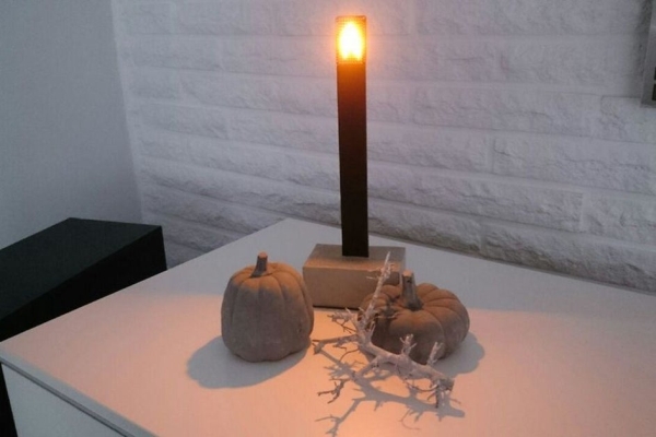
It looks very modern, doesn’t smoke 😉 and can be reloaded with your smartphonecharger.
The yellow light gives you a very good expression of a real flame.
To be exact: it is a video of a real flame which is converted into led-commands.
I came across this idea on several maker-faires and by watching “flame pendent” on adafruit.
While the adafruit is nearly perfect, it doesn’t look elegant or at least like something i would put into my livingroom. And adafruit isn’t the cheapest way to build something.
The ones on the maker-faires where kits. Nothing against kits, but you have to solder every SMD-LED by hand.
And it was quite expensive, too.
You can buy ready-build candles from Ingo Maurer … if you have the money.
————————————————————————————
A bright, modern looking LED-Candle on a budget. Can’t be that hard to build…
Step 1: What You Need
- 3D-printer (or printed parts)
- quickcrete, (concrete)
- arduino pro micro 16Mhz (8Mhz doesn’t work)
- TP4506 LiPo-loader
- Adafruit LED-Matrix (yellow) and PWM Driver
- some 1.5mm aluminium sheets (and a way to bend it)
- double-sided gluetape
- thin wire
- small switch
- one 18650 batterie with soldertips (no cheap ones, choose samsung or panasonic)
- spraypaint (black matt recommended)
The soldering is quite easy.
If you can’t get the aluminium or the 3D printed parts, you can contact me.
I still have some of them. This project didn’t work on the first or even the third try. I’ve changed a lot while building and have some spare parts.
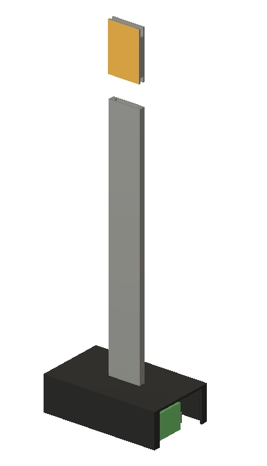
To give you an idea of the construction, have a look at the animation.
Step 2: Print the Parts
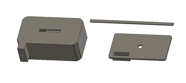
You don’t have to print many parts.
It’s the inner housing and the bottom plate (which contains the switch).
At least 4 little helpers, which will be needed to guide the wire through the aluminium.
After printing you should try if everything fits in. Or at least the Arduino and the TP4506.
If you dont want to use aluminium and may have a better idea, you can change the files, too.
All Fusion360 files are included.
Step 3: The LED-Matrix

Every solderpoint is printed on the modules, so you can’t make many mistakes.
But you need to be carefull. Don’t solder the pins without numbers.
You should solder only one side on the last pins to get the black placeholder on both sides.
So: solder this Pin to the PWM but not to the LED-Matrix.
Have a look at the picture 3. The matrix will be placed on top of the aluminium and “stands” on the placeholders.
I’ve tried several methods. Solder it before adding the shaft? After adding it? None is better.
Cut the pins as short as possible AFTER soldering to get a nice finish.
(This pictures are a little bit older. You don’t need screws anymore)
Step 4: The Shaft
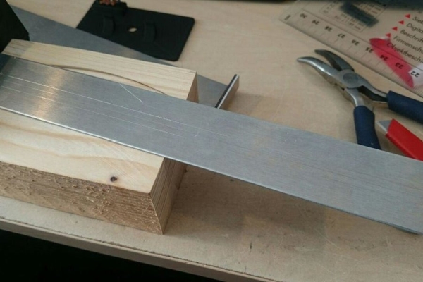
Two bended parts. One of them has to be 5mm longer than the other one. 1.5mm aluminium (very important)
Mine are about 185mm high, 28mm width (important). The bended part is about 18mm long.
That way it fits perfectly between the LED-Matrix and the PWM-Controller.
To fit the cables between those parts, you have to glue the little helpers with double-sided tape on the longer one.
Just mark it with a knife. They should be placed about 3cm higher, so the helpers do reach into the display.
On the bottom they can reach into the housing. That way the hold the batterie in place, too.
But don’t let them get too long into the housing. It’s not much room in there.
Put the wire between the helpers and place the other shaft. As written before: 5mm difference.
You can place the display on top to get a perfect match.
Cut the double-sided tape just under the display and glue the second shaft on the helpers.
Congratulations. This was the first part where everything could have been gone terribly wrong.
Use some thicker double sided tape on the “feets” and peel the siliconpaper of.
Now you have to use some force to push the shafts through the housing. It does fit, but it’s as tight as possible.
Step 5: Molding the Base
I’m a big fan of quick drying concrete. You can mix it quite liquid and it still works very good.
To build the mold, i’m using waterresistant plywood. In Germany they are called “Siebdruckplatte”.
10mm around and 15mm on top of the housing is enough concrete.
Prepare the housing by sealing the USB-Port and with very thin (tesafilm) tape, the shafts.
If you miss this part, the concrete will pour into the shaft. Looks terrible and the concrete will tend to tear apart at exactly that position.
Put good double-sided tape on the bottom plate of the housing. This way the hole thing will stay in place while pouring the concrete into the mold.
Let it dry at least twice the time you think it should have been enough time.
If the base doesn’t look perfect enough you can file the edges or use some sandpaper.
It doesn’t have to be perfect. It’s concrete. It has to have some “errors”.
You need to peel the double-sided tape of the bottom plate. Use a spatula to get it of the wood.
Step 6: Put Color on It
The aluminium should be cleaned with some kind of alcohol.
Using isopropanol is allways a good way to start. You don’t have to grind/sand the surface before spraypainting it.
Just cover the concrete as precise as possible at the entrypoint of the shaft.
And cover the wires and little helpers on top.
Spray two or three very thin layers to get a perfect finish.
Let it dry twice the time as noticed on the spraycan.
At this point i let it cure over night in a warm room before getting to the next steps.
The concrete will change the colour over night.
Step 7: Electronics (in the Box)
Flash the Arduino with the added code. You can try the code from adafruit, but it will not fit. Just a little bit to big.
EDIT: I’ve added another code. It’s one frame smaller. Just in case.
EDIT 2: I’ve added a data.h with rotated frames.
I’ve deleted just one frame and recompiled the code with the python script. Using 99% of space.
28664 bytes … just 6 bytes left.
While you flash you will see three LEDs. One in constant red and two blinking. The constant red LED (near to the usb-Port) should be destroyed with a very small plier. Well, you could change the code, so the LED doesn’t light up, but you can destroy it, too. And i don’t think that there is enough space left for the code. Or you have to delete another frame.
The connections are quite easy.
Arduino -> Display
D2 -> SDA
D3 -> SDL
VCC -> VCC
Ground -> Ground
TP4506 -> Arduino
Out – -> Ground
Out + -> /Switch -> RAW
TP4506 -> Battery
self explaining
Just make sure all wires are long enough. I’m using 10cm long wires.
Solder every solderpat before soldering the wires on them. You don’t want to push the wires through the pinholes.
Just solder them on the pinholes and think of the way the wires will bend, when you have to put all parts together.
Step 8: Electronics and the Display
If you bend the pre-soldered endings from the wires just a little bit, those endings will just slip into the pinholes from the display.
This is the most annoying part in this instructable. You may pull the wires from within the housing to get a better position.
Trust me, it will fit. I’ve made three of them, but couldn’t find a real good solution.
Check your connections twice.
First test. Finally. You will be amazed.
If the display just gives you one random pattern (see picture 1), your batterie is to low.
Now you can peal off the upperpart from the siliconpaper on the helpers and put the display right in place.
As gently as necessary. Everything in place and it still works? Fine. To fix the display finally, you should pour some clear glue from top through the Matrix and the PWM-Driver. Just where the wires where soldered.
The glue will find a way through the wires and glues the Display onto the helpers.
Step 9: Final Assambly
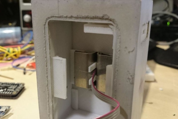
You should bring the Arduino first into position, followed by the TP4506.
There may be too much space for the TP. If thats the case, you can glue it.
You should be able to push a USB-cable into it without moving the TP inside the housing.
Now bring the isolated batterie into it. It’s getting quite full in here. Try to bring the wires down.
All in place, try to put the bottom plate on it. If it doesn’t fit, you can use a plier to break the noses away.
They are just an extra support to the batterie.
Put some feet under it, if you like.
Source: Matrix LED Candle Light
- What components do I need to build the LED-Matrix-Candle?
Use a 3D-printed housing and bottom plate, Arduino Pro Micro 16MHz, TP4056 charger, Adafruit yellow LED-Matrix and PWM driver, 1.5mm aluminium sheets, double-sided tape, thin wire, a small switch, a 18650 battery with solder tabs, spraypaint, quickcrete, plywood mold, and clear glue. - Can I use an Arduino Pro Micro 8MHz for this project?
No, the article states the 8MHz version does not work; use the 16MHz Pro Micro. - How should the aluminium shaft parts be prepared?
Make two bent 1.5mm aluminium parts, one 5mm longer than the other, about 185mm high and 28mm wide, with an 18mm bent section to fit between the LED matrix and PWM controller. - How is the concrete base molded and cured?
Use a plywood mold, leave 10mm around and 15mm on top of the housing, seal the USB port and shafts with tape, secure the housing to the mold with double-sided tape, pour quickcrete, and let it dry at least twice the expected time. - How should the LED matrix be soldered to avoid mistakes?
Solder pins carefully following printed solder points, avoid soldering pins without numbers, solder one side on last pins to keep placeholders, and cut pins short after soldering for a clean finish. - What wiring connections are required between the Arduino, display, and TP4056?
Connect Arduino D2 to SDA, D3 to SCL, VCC to VCC, Ground to Ground; TP4056 Out- to Ground, Out+ through the switch to RAW on Arduino, and TP4056 connects to the battery. - How do I fix the LED matrix in place after testing?
After confirming the display works, pour clear glue from the top through the matrix and PWM driver where the wires are soldered so glue flows along wires and secures the display to the helpers. - What should I do if the display shows random patterns?
If the display shows random patterns, the battery is likely too low and should be charged or replaced. - Is spraypainting the aluminium necessary and how should it be done?
Clean aluminium with isopropanol, cover concrete and wires, spray two to three thin layers, and let it dry twice as long as the can recommends. - How much code space is available on the Arduino for the flame frames?
The project uses most of the space; after optimizing frames the compiled size was 28664 bytes with about 6 bytes left, and a constant red LED near USB was removed to free space.