Summary of Making a Smart BLE Receiver for My Dumb Garage Door
This article details a DIY smart garage door opener that replaces a bulky remote with a Bluetooth Low Energy (BLE) system. Using an Android app and a Reyax BLE module, the user triggers a relay via a NodeMCU to open the door, mimicking the existing wall switch without permanent modification. The project emphasizes security by maintaining a whitelist of paired devices and includes a pairing mode for managing access.
Parts used in the Smart BLE Garage Door Opener:
- Reyax RYBG211_Lite BLE module
- NodeMCU microcontroller
- Mini DC to DC step down module
- 12V Power adapter
- PCB Screw Terminal
- Pin Headers
- Prototype PCBs
- 5V Relay Module
- Mini breadboards
- Project enclosure box
- Soldering iron
- Soldering kit
- Multimeter
- Android phone
My garage door comes with a motor and a 433MHz remote that I don’t always carry with me because it is quite bulky and in the way.
Because of that, sometimes when I am in front of it and I want to open it, I had to go inside and press the trigger switch that is attached to the wall next to the entry door on the inside.
Since I got tired of that, when Reyax approached me and offered to send in a BLE module for me to make a project with it, I knew that now was the right time to solve this for myself.
The final garage opener receiver uses a custom app that I built with MIT App Inventor to send a command to the Bluetooth module and a NodeMCU controller then reads that message. Once the right message is received, a relay is triggered that basically overrides the switch contacts via a relay and opens the garage door.
The entire setup is added as an add-on to the existing door and switch without interfering with it and it can be very easily removed if there is ever a need for that.
Supplies
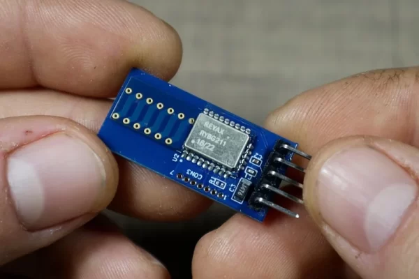
The star of the project is the Reyax RYBG211_Lite module which is used to communicate with the phone and receive its commands. The module can connect to up to 8 devices at a time and it uses AT commands to talk to the microcontroller via UART, making it extremely easy to add Bluetooth support to any project.
The Reyax RYBG211 BLE Module can be found on the links below:
REYAX RYBG211_Lite: https://reyax.com//products/RYBG211_lite
RYBG211_Lite on Amazon: https://www.amazon.com/REYAX-RYBG211_Lite-2-4GHz-Power-Module/dp/B097Y8LSJV
RYBG211_Lite on First Component: https://www.first-components.com/en/rybg211_lite
Other parts and tools needed for the project
- NodeMCU microcontroller – https://s.click.aliexpress.com/e/_DEeYNqr
- Mini DC to DC step down module – https://s.click.aliexpress.com/e/_DDUhdrp
- 12V Power adapter – https://s.click.aliexpress.com/e/_DmERHmf
- PCB Screw Terminal – https://s.click.aliexpress.com/e/_DCwF1xv
- Pin Headers – https://s.click.aliexpress.com/e/_DBtPODh
- Prototype PCBs – https://s.click.aliexpress.com/e/_DldKD71
- 5V Relay Module – https://s.click.aliexpress.com/e/_DEqGEiF
- Mini breadboards – https://s.click.aliexpress.com/e/_DmY9HFv
- Project enclosure box – https://s.click.aliexpress.com/e/_Dkng61v
- Soldering iron – https://s.click.aliexpress.com/e/_DcIXiNv
- Soldering kit – https://s.click.aliexpress.com/e/_DmAl8z1
- Multimeter – https://s.click.aliexpress.com/e/_DB5z2UB
- Android phone – https://s.click.aliexpress.com/e/_DCpBbSn
Step 1: Making the Proof of Concept Circuit
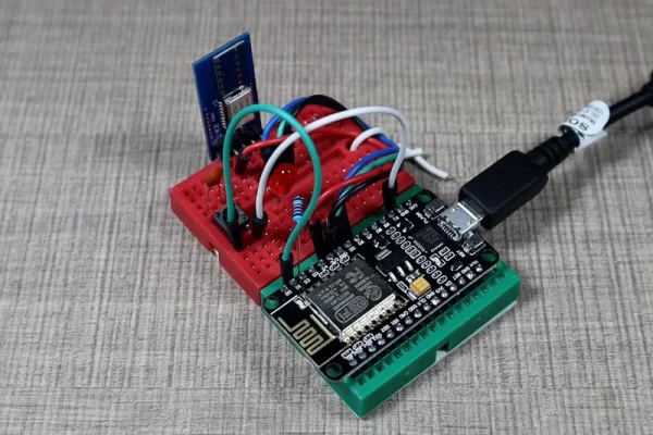
To begin, I first assembled the entire project on a breadboard so I can test out the code and the mobile application. The RYBG211_Lite module is connected to pins D5 and D6 and the software serial library is used to communicate with it.
The relay will be connected to pin D2, but for the POC, I only connected an LED so I can monitor the output when triggered. Most relays are controlled by pulling the pin low, so the LED anode is connected to 3.3v from the NodeMCU and its cathode is connected to pin D2.
In addition to the LED, there is also one push button that is connected to pin D1 so we can then put the entire project into pairing mode and new phones can be connected to it only in a specific time period. This is done so that we add a layer of security and prevent strangers from controlling our door.
Step 2: Creating the Mobile App
The mobile application is created using the MIT App Inventor platform. Since this is just a one-off project and to keep everything simple, the BLE module address is hardcoded inside the code so I made the APK to only work for this module. If you want to create one for yourself, you will need to update this with your module address.
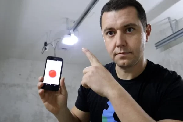
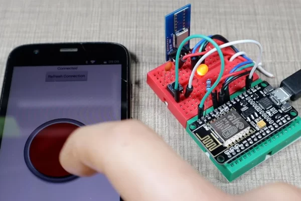
Once the BLE module is connected and paired with the phone, the app has one very simple job and that is to send the “OPEN” string to the module on each button press.
An additional button is added to the top of the screen so that in case the Bluetooth module does not connect automatically, we can manually trigger the connection.
The code for the application can be found in the project repository on GitHub.
I’m not fully happy with how App Inventor works in this example as there were some Bluetooth issues with Android 12 at the time of writing this Instructable but it will have to do it for now.
Step 3: Handling Security
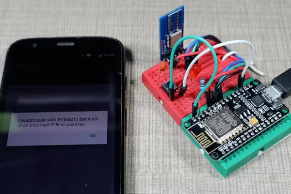
A major part of the project is how to control what phone can connect to the receiver. If we allow all of the phones to connect, someone might come close to the door, connect to it, and then send the right data to the module so the door can be opened.
To prevent this, the project keeps a list of allowed devices. When a connection request is received, the Arduino code checks the allowed devices list to see if the connecting device is in the list and if it is not, then the connection is terminated immediately.
To add a device to the allowed list, we need to press the push button for 5 seconds so we can put the project into pairing mode. The pairing mode is active for 30 seconds and during this period, any new device that connects to the module will be added to the list.
To clear the list of devices, while in pairing mode, we can press the push button again and that will clear out all of the previously added devices.
Step 4: Soldering the Circuit
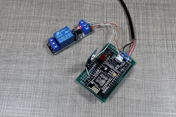
Once I was happy with how the garage door project worked, I used a prototyping PCB to make permanent solder connections. The project will be powered from a 12V power adapter so I used a DC-to-DC converter to reduce the voltage down to 5V to then provide it to the Vin pin on the NodeMCU.
All of the other connections are made as previously explained.
Source: Making a Smart BLE Receiver for My Dumb Garage Door
- How does the system trigger the garage door?
The NodeMCU reads commands from a custom mobile app sent via the BLE module and triggers a relay that overrides the existing wall switch contacts. - Can I use this project on iOS devices?
The article specifies using an Android phone and mentions Bluetooth issues specifically with Android 12 during development. - How do I prevent strangers from connecting to my device?
The code maintains a list of allowed devices and terminates any connection request if the connecting device is not on that whitelist. - What is the best way to add a new phone to the allowed list?
Press the push button for 5 seconds to enter pairing mode, which remains active for 30 seconds to accept new connections. - Does the project interfere with the original garage door mechanism?
No, the setup is added as an add-on that can be easily removed without interfering with the existing door or switch. - How is the power supply managed in the final circuit?
A 12V power adapter feeds into a DC-to-DC converter to reduce the voltage to 5V for the NodeMCU Vin pin. - What platform was used to create the mobile application?
The mobile application was built using the MIT App Inventor platform. - How can I clear the list of paired devices?
While in pairing mode, pressing the push button again will clear out all previously added devices from the list.