One can use a cell phone with any cellular networks around the globe if the proper SIM card is inserted in it. This is possible because there is some device inside the cell phone which follows a global standard enabling them to connect with different cellular networks. This standard is called Global System for Mobile communications (GSM). The mobile phones have built in GSM modules which then be used by the processor inside the phone to make a call, send or receive message or even connect with the GPRS network.
 In certain applications the microcontroller based systems has to be connected with the GSM network which will enable a user to control the system by sending messages or making a call. The systems can also send messages to the user to alert or inform about the status of the system running. In all such cases a separate GSM module is used rather than using the mobile phones. There are GSM modules available which can do serial communication with microcontroller based systems. The communication is done by sending or receiving AT commands.
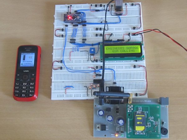
This particular project demonstrates how to interface a GSM module with Arduino and make them to call a particular mobile number. The GSM module in this project is interfaced with the easy prototyping platform Arduino which makes the hardware circuitry simple and easy to write a code using the C based programming environment.
The GSM module used in this project is a SIM900 based module which can communicate with other devices using RS232 serial communication port. It works on 9V power supply and the image of the same is given below:
The Arduino is open source hardware where the hardware schematic is open anybody can use those schematic to develop their Arduino board and distribute. The Arduino IDE is also open source and anybody can contribute their libraries to the Arduino. All arduino boards should be compatible with the Arduino IDE which can be used to program the Arduino boards.
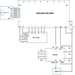
The Arduino board used in this project is the Arduino pro-mini board and the IDE version of the Arduino is 1.0.3 for windows. The image of the Arduino pro-mini board and the Arduino IDE are shown below:
Since the arduino pro-mini board has no circuitary for interfacing it with the serial port or the USB port of the PC, an external USB to TTL converter board is required to connect it with the PC. This hardware helps in programming the Arduino board and also helps in the serial communication with the USB port of the PC.
It is assumed that the reader has gone through the project how to get started with the arduino and tried out all the things discussed there.
Arduino board can act as a stand-alone system with capabilities to take inputs, process the input and then generate a corresponding output. It is through these inputs and outputs that the Arduino as a system can communicate with the environment. The Arduino boards communicates with other devices using digital input/output analog input/output standard communication ports like USART, IIC, and USB etc.
In this particular project the GSM module is connected with the Arduino board using the serial communication port. Since the module has RS232 port and the Arduino pro-mini can communicate using TTL logic levels a max232 IC is used to make a bi-directional conversion between the RS232 and TTL logic levels. The Tx pin of the Arduino board is connected to the Rx pin of the GSM module through the max232 and the Rx pin of the Arduino is connected to the Tx pin of the GSM module using max232 itself.
The code written in the Arduino is able to communicate with the GSM module using AT commands. The AT commands are send or received from the module using the serial communication functions provided by the Arduino library. The functions like Serial.begin() which helps to initialize the serial port with a given baud rate, Serial.write() to send a data to the serial port, Serial.available() and Serial.read() functions to read data from the serial port are used in this project and they are already discussed in previous projects on how to do serial communication with the Arduino, how to send and receive serial data using arduino and how to do serial debugging with the Arduino.
GSM modules respond “OK” when it receives the command “AT” and it is the best way of check communication between the module and the microcontroller. The command for making a call to a number is “ATD”;
SYNTAX: ATD<Phone number>;(Enter)
For example,
ATD123456789;
 Try to send the command using the PC with the help of any serial monitoring software and make sure that the module is making a call to the specified number. Then one can verify and upload the code which can send the same commands to the Arduino board as explained in the project how to get started with the Arduino. Once the board is reset after successfully uploading the code the Arduino sends the same command to the GSM module enabling it to make a voice call to the number specified in the code.
Make sure that the GSM module has been turned on at least 2 minutes before the Arduino board start sending the commands so that the GSM establish a communication with the cellular network corresponding to the SIM card inserted in it.
For more detail: How to Make Phonecall From GSM Module Using Arduino