With the attached breadboard, you can do more electronics experiments, fool around with different sensors, etc. This project can teach you about electronics, programming, and robotics. It is also a fun toy to entertain younger siblings and pets (just be sure they don’t break it!).
Here is a video of what MAEP will do when it is done:
Step 1: Parts
– Arduino compatible microcontroller. I used an Arduino Uno, so I recommend one if you wish to follow closely along with this tutorial. There are also some Arduino based controllers that are designed specifically for robotics that may be helpful, but you’ll have to find your own method of mounting those. You can buy a copy of the Uno from YourDuino which I believe is completely compatible: http://arduino-direct.com/sunshop/index.php?l=product_detail&p=5
– Breadboard. Make sure it’s not too big, or else it won’t fit. However, we want it to be as big as possible so we have more room for electronics. This is good: http://arduino-direct.com/sunshop/index.php?l=product_detail&p=168
– A standard old 9 volt alkaline battery (which you can probably find at home), as well as a barrel jack connector to hook it up to your Uno easily (not required, but again, easier): http://arduino-direct.com/sunshop/index.php?l=product_detail&p=119
– A power supply for the motors. I don’t believe the power supply I chose is the cheapest or best option, so I’m not going to recommend it to you. I used a 4.8 volt rechargeable NiCad battery, but it’s probably easier to just use a 4 AA battery holder (no need to buy a charger that way)
– A bunch of Boe-Bot hardware for the chassis. Unfortunately, you can’t get this from YourDuino, so look at Parallax, the manufacturer’s website. You can choose either to buy this: http://www.parallax.com/StoreSearchResults/tabid/768/List/0/SortField/4/ProductID/304/Default.aspx?txtSearch=boe+bot+chassis which comes with tons of extra components you don’t need (although may be useful someday), or you can buy all the components in the following list from Parallax and no, I’m not gonna provide a link for each one:
Stock # Quantity Product Name
700-00002 8 Panhead screw, 4/40, 3/8
700-00003 8 4/40 x 3/8″ Nut
700-00009 1 Tail Wheel Ball
700-00015 2 #4 Nylon Washer
700-00022 1 Boe-Bot Aluminum Chassis
700-00023 1 Cotter Pin-1/16″ Diameter
700-00025 1 Rubber Grommet-13/32″ Hole Diameter
700-00028 4 Panhead screw, 4/40, 1/4
700-00060 2 Standoff, threaded aluminum, round 4-40
721-00001 2 Wheel, Plastic, 2.58 Dia, .3 W
721-00002 2 Rubber Band Tire for 721-00001
900-00008 2 Continuous Rotation Servo
– Wire to hook things up will be necessary. Some male-to-male jumpers will do the trick: http://arduino-direct.com/sunshop/index.php?l=product_detail&p=94
– Finally, the PING))) sensor and mounting bracket, so that your robot doesn’t kill itself: http://www.parallax.com/StoreSearchResults/tabid/768/List/0/SortField/4/ProductID/563/Default.aspx?txtSearch=ping+sensor+mount
As for tools, all you need is a phillips head screwdriver, a computer, and one of those standard USB printer cables. The Arduino Uno I provided a link for has a cable included.
Now lets get building!
Step 2: Centering Servos
Actually, before you do that, you need to set up the Arduino with your computer! Go do this quick little tutorial here: http://arduino.cc/en/Guide/HomePage, and then come back (I’ll be waiting).
Finished? Good! You should now be able to get your Arduino blinking an LED. Now, you’re going to get it to center your servo motors. Download the attached Arduino file (.ino) and open it with the Arduino IDE. Next hook up your servo motors like in the picture. The black wire should be connected to ground on your Arduino (labeled “GND”), the red one to 5 volts (labeled “5V”), and the white one to pin 11 (labeled “~11”). Make the connections from the Arduino pins to the servo with some male-to-male jumpers.
Now, upload the program to your Arduino board. Once it runs, one of two things will happen:
1) Your motor won’t spin: You’re done! Now go back and repeat for the other motor.
2) Your motor will spin. Adjust the potentiometer (see picture 2) with a phillips head screwdriver to stop it from spinning. Slowly turn the screwdriver in either direction until you find the setting that makes it stop. Remember to be gentle and turn slowly… otherwise you’ll probably overshoot and have to turn the screwdriver the other way.
 Center_Servo.ino127 bytes
Step 3: Attach the Arduino to the Chassis
Once you have the standoffs firmly attached to your Arduino, line up the bottom one with the bottom of the backmost mounting strip (um… just look at the picture). Attach that into place, then line up the front standoff with the next mounting strip, and screw that in place. Yippee, you’re done!
Note: There’s a zip-tie in the picture because I did step 4 before this one… then realized that it’s easier to do this step first.
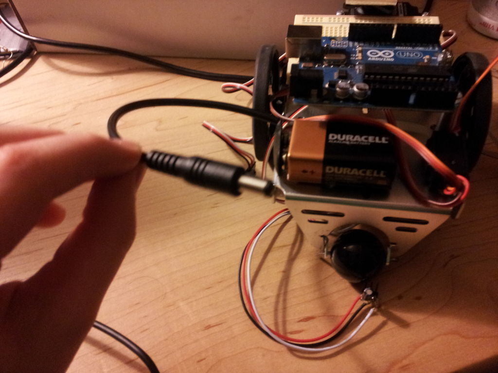
Step 4: Attach the Motor Battery
– If you’re using a 4 AA battery pack, use the screw holes on the chassis
– I used a zip-tie through some of the mounting slots to attach the NiCad battery I used
– Double sided tape
– Velcro
– Used chewing gum
Also, insert the little black rubber grommet into the hole in the center of the chassis and route the battery wire through that.
Step 5: Motors!!!!!
Using the eight 3/8 inch panhead screws and nuts, attach the two continuous rotation servo motors to the chassis. Insert them into the cut-outs from the inside of the chassis, and then secure them firmly in place with the motor shaft towards the back of the robot. Use the pictures as a reference.
Once you have that done, thread the wires from the motors up through the hole in the middle of the chassis. Pop a wheel onto each motor shaft, and using the screw that attached the servo horn, attach the wheels to the motors.
Step 6: Tail Wheel
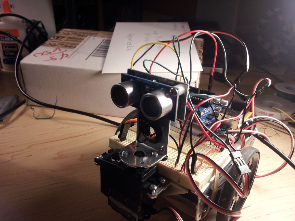
Step 7: De-blinding the Robot
Note: In the pictures you’ll see something attached to the bottom of the motor that my PING))) sensor is mounted on. Ignore it, it’s from another project I did with this robot.