Summary of Make a Musical Bench using Arduino
The Musical Bench uses an Arduino and a Musical Instrument Shield to detect changes in human body resistance via copper touch pads and play high or low notes. The project replaces the original prototype board with an Arduino, wiring resistors, a capacitor, and three signal wires to sense touch through the shield and drive audio output. It’s intended for benches, fountains, or playful experiments with conductivity and capacitance.
Parts used in the Musical Bench:
- Arduino USB (any type)
- Sparkfun Musical Instrument Shield
- Arduino Stackable Header Kit
- Two 1k Ohm resistors
- One 39k Ohm resistor (or 47k substitute)
- One 0.1 uF capacitor
- Solid core wire (red, black, white)
- Stranded wire
- Two touch pads (copper/brass scraps or conductive objects)
- DC power supply 9-12V
- Speakers or headphones with 1/8" stereo jack
- Soldering iron
- Solder
- Wire stripper
- Wire cutter
- Safety goggles
- Computer with Arduino software
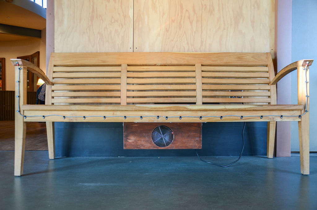
The Musical Bench is an exhibit which makes music when people touch, kiss, or hold hands. It uses a micro-controller to detect changes in resistance, via the copper armrests, and plays high or low notes depending on how much current flows through you and a friend. This exhibit is the result of messing around with many different ways of using the human body to complete an electrical circuit.
The original Exploratorium exhibit runs on a prototype board, but for this instructables we’ve used an Arduino instead. This makes it possible for you to build it into a bench, a drinking fountain, or something that we haven’t thought of yet. You can also use this as a personal tool for playfully investigating electricity, conductivity, and capacitance. Have fun and happy tinkering!
Step 1: Materials
Collect these parts:
- Arduino USB (any type will work)
- Sparkfun Musical Instrument Shield
- Arduino Stackable Header Kit
- Two 1k Ohm resistors
- One 39k Ohm resistor (you can use a 47k resistor from this set if you can’t find a 39k)
- One 0.1 uF capacitor
- Solid core wire (red, black, and white)
- Stranded wire
- Two Touch Pads (you can use scraps of copper or brass, copper pipes, or other conductive objects)
- DC power supply 9-12V
- Speakers or headphones with ⅛” stereo jack
Tools:
- Soldering iron (we like this one from Weller)
- Solder
- Wire stripper
- Wire cutter
- Safety goggles
- A computer loaded with arduino software
If you are new to Arduino Programming here are some helpful links:
How to program an Arduino http://arduino.cc/en/Main/Software
What an Arduino is http://arduino.cc/en/Main/ArduinoBoardUno
How to choose an Arduino https://www.sparkfun.com/arduino_guide
If you’re familiar with schematics
Here are two schematics that should help most experienced arduinio/electronics people figure out how we’re making. One is a drawing of the connections done with Fritzing, and the other is an electronics schematics of the sensor interface.
Step 2: Solder the headers
The musical Arduino shield is capable of generating sounds, but first we’ll need to set it up so it can take inputs from the physical world and communicate them with the main Arduino board. The first step is to solder on the headers that connect it to the main board.
Insert the pins of the headers into the round holes along the side of the Shield. Make sure pins are down and pointing away from the side of the shield with the components on it.
Flip the shield over.
Solder each pin to the round hole.
Take care to keep the pins straight, these will go into the corresponding sockets of the Arduino board.
Step 3: Add your resistors
- Orient your shield so that you’re looking at the side with the components on it, and the text “Sparkfun.com” is right side up.
- Place the three resistors next to each other in the center of the prototype area of the Musical Instrument Shield. Place the 39k resistor on the left—we’ll call this R1. Place one of the 1k resistors in the middle (R2), and the last 1k resistor (R3) on the right, nearest the audio jack. It helps to spread the legs with two spaces in the middle so that the resistors can lay flat.
Flip the board over. Solder each leg into place. Don’t snip the ends yet.
Cross over the legs of R1 and R2 on the side closest to the audio jack and solder them together.
Step 4: Add your capacitor
Flip the shield over again. Place the capacitor (C1) above the resistors, just on top of R2 and R3.
Flip the shield to the back, and solder C1 down.
Solder a leg of C1 to the adjacent end of R2.
Solder the other leg of C1 to the adjacent end of R3.
Step 5: Add the red wire
Now you will add three wires to the board. To keep them easily identifiable we’ve used red, white, and black but the color of the wire doesn’t matter.
Cut a piece of solid core wire (we used the red one) about 2” long and strip both ends.
Insert one end into board right next to C1 and directly above R1.
Flip over the board and solder that end into place.
Bend down the leg of R1 (the side not connected to R2) and solder it to the red wire.
Flip the board back to the front and insert the other end into the header socket labeled “AREF” (it is on the bottom left side of the shield).
Step 6: Add the black wire
Cut a piece of solid core wire (we use black) about 2″ long and strip both ends about 3/8″.
Insert one end into the board just above the C1/R3 junction.
Flip the board over and and solder the end into place.
Make a soldered connected to the adjacent C1/R3 junction.
Flip the board back to the front side and insert the other end of the wire into the header socket labeled “GND” (right above “AREF”).
Step 7: Add the white wire
Cut a piece of solid core wire (we use white) about 3″ long and strip both ends about 3/8″.
Insert one into the board just above the c1/R2 junction (just to the left of the black wire)
Flip the board over and solder the end of the wire in place.
Make a soldered connection to the adjacent C1/R2 junction.
Flip the board over and Insert the other end of the wire into the header socket labeled “A0” (on the middle right side of the shield).
Step 8: Connect the wires for the touch pads

Cut two pieces of the stranded wire as long as you will need to reach from the shield to where you want the touch pads to go.
Strip back 1/4″ on one and insert just below R3.
Flip the board over. Solder the wire in place and make a soldered connection to the leg of R3.
Go back to the front of the board. Strip back 1/4″ on the other wire and insert just below R2.
Flip the board over. Solder the wire in place and make a soldered connection to the R1/R2 junction.
For more detail: Make a Musical Bench using Arduino
- What does the Musical Bench do?
It makes music when people touch, kiss, or hold hands by detecting changes in resistance and playing high or low notes. - What micro-controller is used in this instructable?
An Arduino is used instead of the original prototype board. - Which shield generates the sounds?
The Sparkfun Musical Instrument Shield generates the sounds. - Which Arduino input pin is used for the sensor signal?
The A0 header socket is used for the sensor signal (white wire). - Where is the reference wire connected on the shield?
The red wire is connected to the AREF header socket. - Where should the ground wire be connected?
The black wire is inserted into and connected to the GND header socket. - What resistors and capacitor are added to the Musical Instrument Shield?
Two 1k resistors, one 39k resistor (or 47k substitute), and one 0.1 uF capacitor are added. - How are the touch pads connected to the shield?
Stranded wires are soldered to the board at the R3 leg and the R1/R2 junction and routed to the touch pads. - What power supply voltage is required?
A DC power supply of 9–12V is specified.