Summary of X-Track – Wireless music visualization and tracker
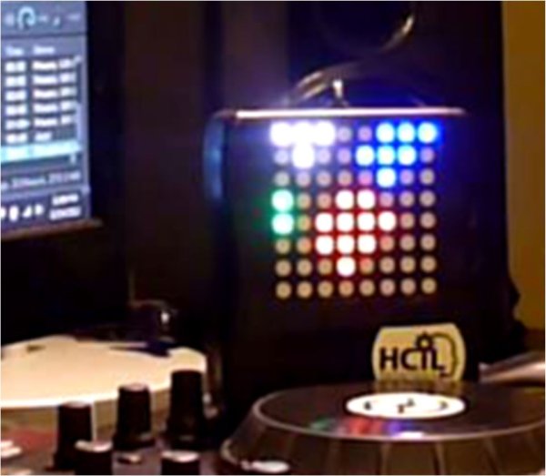
X-Track is a wearable prototype that wirelessly syncs bright, beat-synched LED visualizations to music while logging motion with an accelerometer so users can review which moments moved them. A PC/DJ software analyzes BPM and broadcasts high-resolution beat-phase messages to multiple gadgets via radio; devices display visuals (tempo-locked, responsive to scratching) and send crowd sensor data back for logging. The small Arduino-based units (11x9x3 cm) support many synced devices limited by radio bandwidth.
Parts used in the X-Track:
- Arduino Fio
- ATmega328P microcontroller (on Arduino Fio)
- Polymer Lithium Ion battery (3.3V)
- FTDI cable or breakout board (for programming)
- LED Matrix - Serial Interface - Red/Green/Blue (SPI)
- Triple Axis Accelerometer Breakout ADXL335
- 5V step-up regulator for the LED matrix
- Wiring and connectors (power, GND, MOSI, CS, SCLK, analog pins)
- XBee socket/radio module (implied by Arduino Fio Xbee socket)
X-Track is a prototype wireless device which connects you to the music, by providing entertainment with its bright beat-synched LEDs and tracking your moves so that you can later learn how much you enjoyed the night, and which parts were especially moving you.
Remote wireless visualizations fully synced to the beat:
* Supporting dynamic control of song playback.
** You can adjust tempo and the visual will always be on the correct beat, and you can even scratch !!
* DJ software automatically analyses song bpm (beats per minute), aligns the beats with the song, and send the high-resolution beat phase messages to external control application.
* The external application on PC broadcasts beat time information to all gadgets in the scene.
Live crowd tracking:
* By making use of the additional sensors (accelerometer), each gadget sends crowd information back to the main PC for logging and any other purposes.
Small form-factor:
* The gadget prototype comes in a small package (11x9x3cm). Great for hand-held interaction or wearing around your neck. Future makes can come in smaller form factors to have a less constraint on your fun.
Support for multiple remote gadgets:
* You can have a a high number of synced displays in a single room, and you can gather sensor data from all (the number of devices is limited by the bandwidth of radio communication. Each device sends sensor readings back to the main computer. The practical limit for efficient data acquisition is not yet studied.)
This instructable was made as part of the final project requirement in the CS graduate course “Tangible Interactive Computing” at the University of Maryland, College Park taught by Professor Jon Froehlich. The course focused on exploring the materiality of interactive computing and, in the words of Hiroshii Ishii, sought to “seamlessly couple the dual worlds of bits and atoms.” Please see http://cmsc838f-f12.wikispaces.com/ for more details.
Step 1: Hardware & Wiring Info
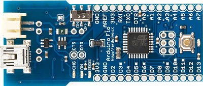
Arduino FIO
* http://arduino.cc/en/Main/ArduinoBoardFio
* https://www.sparkfun.com/products/10116 ($25)
Microcontroller: ATmega328P
Clock Speed: 8 MHz
Operating Voltage: 3.3V
Input Voltage: 3.35 -12 V
Pro’s:
* Includes an Xbee socket already (saves $10)
* Polymer Lithium Ion Batteries from sparkfun provide 3.3V, no step-up component (3.7 to 5V) needed (saves $6)
* Includes battery charger using USB port (saves 10-15$)
Con’s:
You’ll need a 3.v to 5.v stepper for the display (costs 5$)
No direct programming interface available. You need to use FTDI cables/breakout boards.
The longest dimension is slightly bigger than the LED matrix
LED Matrix – Serial Interface – Red/Green/Blue (The Visuals)
* https://www.sparkfun.com/products/760 ($59.95)
* Communicates through SPI serial input protocol
* Runs on 5V (if you don’t raise up the voltage from 3.3 to 5V, you get very pale colors, and an unstable refresh rate)
* Current: 120mA (typical) 275mA (max)
* Dimension: 2.38×2.38″x0.78”
Wiring: (Using SPI Interface)
* VCC(5V)<->5V
* GND<->GND
* MOSI<->PIN11
* CS<->PIN10
* SCLK<->PIN13
Triple Axis Accelerometer Breakout – ADXL335
* https://www.sparkfun.com/products/9269
* “Low noise and power consumption (320uA)”
* Sensing range: +/-3g.
* Power in between 1.8-3.6V
* Bandwidth: 50Hz
Wiring:
* 5V/GND : as usual
* X<->Analog Pin 0, Y<->Analog Pin 1, Z<->Analog Pin 2
Fo more detail: X-Track – Wireless music visualization and tracker
- How does X-Track sync visuals to music?
DJ software analyses song bpm and sends high-resolution beat phase messages to an external PC, which broadcasts beat time information to all gadgets so visuals are beat-synched. - Can X-Track adjust tempo and remain on beat?
Yes, the system supports dynamic control of song playback and the visual will stay on the correct beat even when tempo is adjusted. - Does X-Track track crowd movement?
Yes, each gadget uses an accelerometer to send crowd information back to the main PC for logging and other purposes. - What microcontroller and board are used in the prototype?
The prototype uses an Arduino Fio with an ATmega328P microcontroller. - What LED matrix is used for the visuals and how is it connected?
A SparkFun serial RGB LED matrix is used; it communicates via SPI with connections VCC to 5V, GND to GND, MOSI to PIN11, CS to PIN10, and SCLK to PIN13. - What accelerometer is used and where is it wired?
The ADXL335 triple-axis accelerometer breakout is used, with X to Analog Pin 0, Y to Analog Pin 1, and Z to Analog Pin 2. - Why is a 5V step-up required?
The LED matrix runs on 5V; without raising voltage from the Arduino Fio 3.3V, colors are pale and refresh rate unstable, so a 3.3V to 5V step-up for the display is needed. - How many devices can be supported in a room?
The system supports a high number of synced displays, limited practically by radio communication bandwidth; the exact limit is not yet studied.