Summary of How to make a LED 7-segment display with or without Arduino
Summary: The author built a custom 7-segment display from 27 LEDs on perfboard controlled by an Arduino to make countdowns, basic text, and other effects. Each segment uses three LEDs wired in parallel with shared cathodes; the Arduino multiplexes rows to form digits. The project required planning, soldering, and programming; lessons included using individual resistors per LED and improved soldering and Arduino skills.
Parts used in the 7-segment LED display project:
- Perf board (main)
- Smaller strip of perf (optional)
- 27 LEDs (white or other color)
- Arduino (with USB cable and power)
- 50k potentiometer
- Various jumper wires
- Resistors (author recommends one per LED, though initially used fewer)
I will demonstrate how to create a 7 segment display using LEDs. Use Arduino in conjunction to make countdown timers, basic text displays, and additional features. I enjoy creating unique projects. I looked through all of instructables and couldn’t find anything similar to this. Actually, I looked on Google but found no results. This idea crossed my mind when my actual 7-segment display wasn’t functioning. Have fun!
The things you can achieve with LEDs are truly impressive!
The operational process of the project:
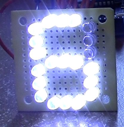
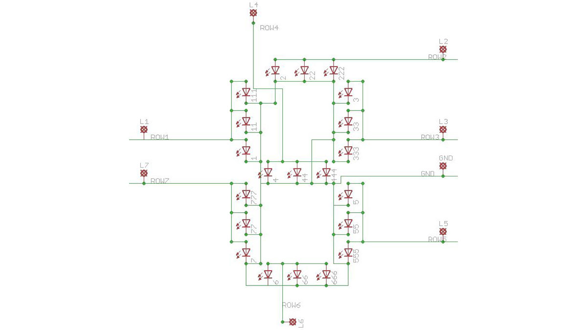
All anodes in a single row are joined. One row consists of 3 LEDs. View image. When voltage is provided to the row, the entire row will illuminate.
Therefore, by linking all the cathodes and utilizing Arduino, I programmed each row to switch on and off. In the image shown, Arduino is activating rows 1, 2, 4, 5, 6, 7.
Don’t forget, in instrucables the pictures are shown before the explanation.
If you want to undertake this project, make sure to carefully review this entire guide before beginning to avoid any confusion! And, be sure to check out all of the photos and their corresponding boxes as well.
Here is a video showcasing my numerical display. Alpha is the next word being shown.
1. What did you make?
The idea started when I was getting frustrated because I couldn’t get my 7 segment display to work with one of my ICs, so I decided upon making my own, so that I’d could control it in basically any way I wanted, including simple text.
2. How did you make it?
The very first thing I did was get out my sketchbook and draw down my ideas, and how I would connect them together.
I started working on this project at 11:30 pm, and kept on going until about 4:30 A.M.. I kept on running into obstacles, such accidentally soldering the negative and positive leads of 3 LEDs together! I made it with 27 LEDs, a small piece of perf board, some basic tools, wires, and most importantly my newly-bought Arduino. I did this project by myself.
3. Where did you make it?
Well. . . I made this project all in my room, on my makeshift desk,and downstairs in our office (for programming Arduino). The more I programmed, the more problems arose, so I had to keep on running back and forth between my soldering un upstairs and the computer down stairs! I wore a path through my carpet, down the creaking wooden stairs, across the tile, over the wooden floor in my office to the computer. How did the project connect to other activities in my life? I was able to count this for my schoolwork! I aslo used this project as a show-off to Bravo, (another group in my activities, I’m ALPHA)
4. What did you learn?
- Where do I start? I learned that I should have used a resistor for each LED, instead of one resistor
- The BIGGEST thing I learned was how to program my Arduino!
- I learned some more techniques about soldering
- I also learned a little bit more about LEDs themselves
If I could do anything differently i would have bought 27 resistors and soldered them to each LED!
What am I proudest of? My success! I would have never thought it woud be such an interest with my friends!
 Remove these ads by Signing Up
Step 1: Ingredients:
What you will need:
TOOLS:
1x Wire strippers & snipers
1x Solder
1x Soldering pencil
1x Wire strippers & snipers
1x Needle-nose pliers
1x Solder
1x Soldering pencil
You may need some wire cutters other than the ones on the stripper. See step 5.
Something to cut perf board
PARTS:
1x Perf Board (http://www.radioshack.com/product/index.jsp?productId=2104052)
1x Smaller strip of perf (not necessary, but recommended)
ELECTRONICS:
21x White (or other color) LEDs
1x 50k pot (potentiometer)
1x Arduino & USB cable & power (optional)
Various jumper wires, MAX, 9
Step 2: Getting Familiar With The Design
Step 3: Prepping the Perf Board
Now we will need a template of some sort to help us arrange the LEDs. Get your perf and place the LEDS in the holes, like the picture. Then, taking them out, use a black marker to draw where the LEDs will go. Now what I’m about to say is kinda hard to say with text, so bear with me. There is a specific reason why I put the LEDS in the manner that they are. You might be wondering, why didn’t I put the LEDs sideways. Well the reason being is that The LEDs have a little notch on the cathode side. Since the LEDs are a tight fight, this little flat end on the cathode enables the other LED to push up right next to it. If they were laid out sideways, there would be no flat groove, and the LEDs would not sit all together flat on the board since they are too close to each other. Try it out, and you will see what I’m talking about. I HOPE you understand!
I added some photos of how the LEDs fit. The first picture is of them vertically, and the second is of them sideways(horizontally).
- What did you make?
A custom 7-segment display made from 27 LEDs controlled by an Arduino to create countdowns and basic text. - How are the LEDs arranged for each segment?
Each segment consists of three LEDs wired in parallel in a single row with their anodes joined. - How are the cathodes handled?
All cathodes are linked so the Arduino can switch individual rows on and off. - What tools were used?
Wire strippers/snippers, solder, soldering pencil, needle-nose pliers, and something to cut perf board. - What electronic parts are required?
Perf board, 27 LEDs, 50k potentiometer, Arduino with USB cable and power, and various jumper wires. - What programming is involved?
The Arduino is programmed to multiplex rows to form digits and display simple text and countdowns. - What did the author learn from the project?
The author learned to program Arduino, improved soldering techniques, more about LEDs, and that using a resistor per LED would be better. - Why were LEDs placed vertically instead of sideways?
Vertical placement uses the LEDs cathode flat notch so LEDs fit tightly and sit flat on the perf board. - How many resistors should be used per LED?
The author recommends using one resistor per LED instead of a single resistor for multiple LEDs.