This project is the perfect way to level-up your pumpkin carving and reach new high scores. Using an addressable LED strip and an Arduino, you’ll be able to make a basic screen capable of playing Pacman, and a controller made of a smaller pumpkin. This was a long process so give yourself plenty of time (and room in the fridge to store your creation) to get things working.
Supplies

Lay out your materials!
- One large pumpkin
- One sugar pumpkin
- An Arduino Mega (Arduino Uno untested but success depends on program size)
- An addressable LED strip (with a density of 60 LEDs/m)
- An Arduino-compatible joystick module
- A momentary switch
- A power supply
- Cardboard
- Black presentation-board
- Letter paper
- Toothpicks and wooden skewers
- Small length of string
- Masking tape
- Black duct tape
- Lots of wire (preferably at least 3 different colours)
- Window film (or any LED diffuser alternatives)
- A piezo speaker
Get your tools:
- Box cutter knife
- Soldering iron and gear (flux included!)
- Automatic wire stripper
- Wire cutter
- Scissors
- Pumpkin-carving knife
- Markers
- Metre-stick/ Measuring tape and T-square
Step 1: How Big a Screen Can You Get?
Before putting together your screen, you’ll need to know how big your screen can be. Unfortunately the day 1 pictures was lost from a faulty SD card, but it was simple enough.
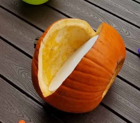
After gutting the large pumpkin from the bottom, figuring out the matrix size just means cutting the shape of the mouth. Our pumpkin had a 60° mouth angle (before shaving in the later steps).
To sketch the cut, choose the front of your pumpkin and make a mark on the left and right side of your front. You want the points on the pumpkin where the bottom of the mouth will meet the top.
Then, using string and masking tape, you can mark out a curve from one point to another. Cut along the drawing and your mouth is cut!
To measure out our matrix we used a piece of foam, but carboard, a meter-stick, or a measuring tape would work fine. The goal is to find the right sized rectangle you can fit in the mouth so you can get an idea of how many LEDs you can fit inside. In our case we could fit 13 rows so 169 LEDs!
Step 2: Making the Matrix
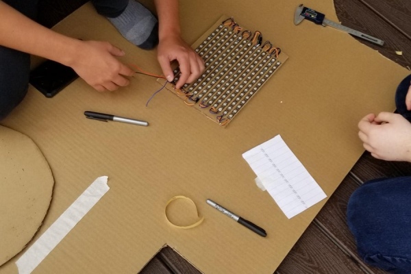
Start cutting your LED strips into whatever length you can fit in your pumpkin. We cut 13 lengths of 13 LEDs which we then taped down to some cardboard. Do not use the LED strip’s adhesive backing to stick the LEDs to the cardboard as this part is temporary, masking tape works fine.
You’ll notice arrows on the LED strips, these indicate the flow of current when the lights are powered on. You’ll want to organize your LED strips in a way that allows for the arrows on the strips flows through the entire screen.
Once it’s laid out you have to solder it together. This is a long and frustrating process but using the right amount of flux you’ll be able to make clean joints that will remain strong and disconnected.
Once you’re confident in your soldering job add on some extra long wires at the first LED strip to give power, signal, and GND to the entire screen. If you want to test your matrix, you’ll need a power supply first (see next step), and you’ll have to wire your matrix as shown in the attached diagram, and run the attached sketch. Matrix size won’t matter you’ll just need to change the NUM_LEDS variable in the code to however many LEDs your matrix has.
If your display works, cut a sheet of cardboard to hold your matrix and start peeling the adhesive off the LED strips. To get the maximum screen space out of your pumpkin you’ll need to make the cardboard as small as possible while still being able to hold all the LED strips. To get regular spacing between the LED strips you will want to measure out the distances between each strip. We used a 4.5mm piece of paper to mark out the separation between the LEDs which worked great!
Step 3: Sorting Out Power
Our pumpkin had 169 LEDs so we definitely wanted to have a bigger power supply on hand. At low brightness settings you might be able to get away with powering the screen solely from the Arduino but an external power supply is sure to give enough power no matter what brightness you’re going for.
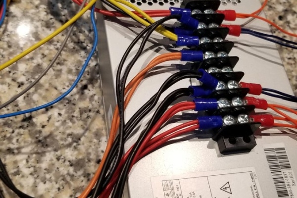
I’ve used an old computer power supply which gives me plenty current at 5V to power the LEDs.
To put together the power supply for this project I simply cut the ATX power connector, wired a switch between a GND wire and PS-On (to give the needed signal to turn on and off the power supply) and wired the remaining red and black wires (+5V and GND) through a screw terminal for ease of access!
Step 4: Housing the Matrix
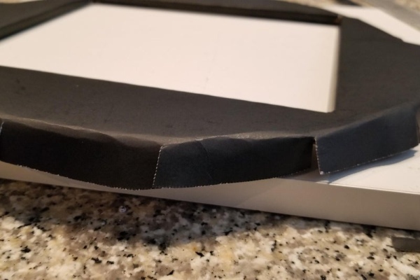
Your LED matrix is ready and working! Now you’ll want to diffuse the LEDs to give off a softer light and hide the LED strips.
I used two layers of masking tape and window film. Using masking tape I’d move along the width of the matrix, taping over the lights and making sure not to overlap any tape. Once I’d wrapped the screen in tape once vertically and once horizontally, I’d wrap the window vertically around the screen and tape the film onto the cardboard at the back. The result is a perfectly diffused screen that can get moved around without breaking any flimsy soldering connections.
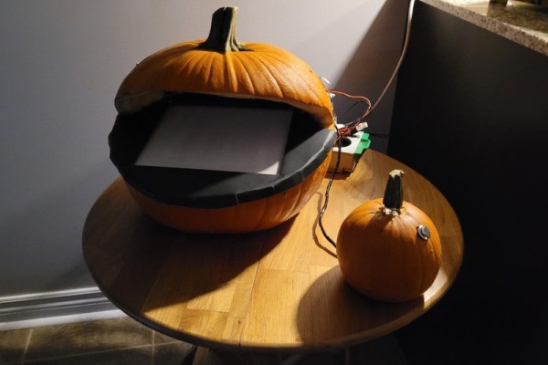
Next you’ll want to build the screen’s housing to make it look nicer inside the pumpkin:
- Using paper as a stencil, draw out the shape of the inside of the pumpkin
- Cut out a piece of cardboard from that stencil so that your cardboard will divide the empty space inside your pumpkin in two
- Cut a whole in your cardboard to fit the LED panel you’ve made
- Use duct tape to connect the diffused LED panel with the new housing
- Use the cardboard housing as a stencil to cut out a piece of black presentation board of the same shape but with extra material to be folded over the edge of the cardboard
- Cut a slightly smaller whole in the center of the presentation board to show the LEDs while also making tabs inside the hole that will fold over the cardboard housing
- Fold over the edges of the presentation board, making regular cuts and using duct tape to hold the folds on the back of the housing
- Duct tape one end of the long wires you’ll need to connect the Arduino to the LEDs to the back of the housing so that you can’t accidentally pull the wires off the matrix
You should now be left with a beautiful looking housing for your LEDs!
Step 5: Cutting a Controller
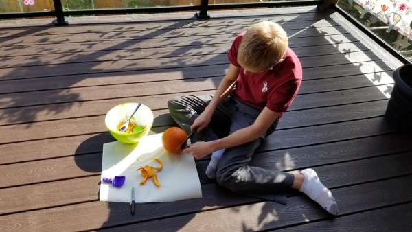
The original plan was to mount the controller to the top of the large pumpkin, but using the sugar pumpkin definitely makes things neater. Just like with the larger pumpkin you’ll want to start gutting from the bottom. We’ll use the stem of the pumpkin as the joystick so we must keep the top of the pumpkin intact.
With the pumpkin gutted from the bottom, you’ll want to cut a small rectangular hole in the top of the pumpkin, just large enough for the joystick. Don’t install the joystick yet, but keep it’s size in mind.
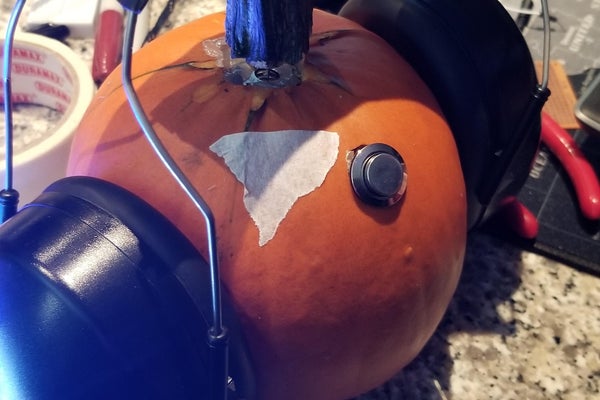
Then cut the stem off of the pumpkin and drill a hole to connect the joystick to the stem. I 3D printer an adapter from the joystick to the stem but a smaller hole would have produced the same results and held on tightly to the stick. Take off the stem for installing
Finally drill a hole into the side of the pumpkin to hold your button. From our experience we were able to cut our hole then install the button from the outside where it would stay in place without the need for any pins, glue, or tape (not that we wanted to try sticking anything to the inside of a pumpkin).
Step 6: Wiring the Controller
To minimize the need for us to click down on the fragile stem of the pumpkin, we wanted to use the external momentary switch. This meant we needed wire long enough to connect the joystick to the Arduino outside the pumpkin, and parts soldered together inside the pumpkin to get the button working.
We soldered and labelled five wires of equal length to the joystick so that we’d be able to connect to the Arduino from quite the distance. We then soldered a resistor between the GND pin of the joystick and the pin that would carry the output of the button. Another wire was soldered to the +5V pin of the joystick and finally a wire was connected at one end to the button output wire. The button connected the +5V wire and the loose wire connected at one end to the button output pin.
Ultimately we had a similar circuit to the Arduino button circuit shown but had much longer wires and were using the same power source from the joystick instead of running extra wires solely for the button.
We installed the joystick and button from the pumpkin, and secured the joystick in place with tooth picks and wooden skewers. We put the stem back on top of the joystick and taped the wires coming out of the pumpkin to not rip parts out of the pumpkin, and the controller was officially done!
Step 7: Programming
Before installing the parts into the pumpkin, you’ll definitely want to test your creation. I’d encourage playing around with the FastLED library to control the led matrix and the analog joystick reading but if you don’t want to play around with the code that’s ok too!
Attached I have the final code which will let you test the controls and play the game.
Upload this sketch and prepare to put everything together!
NOTE: “notes.h” is an external library you can install by following: https://www.instructables.com/How-to-Add-an-External-Library-to-Arduino/
Step 8: Putting It Together
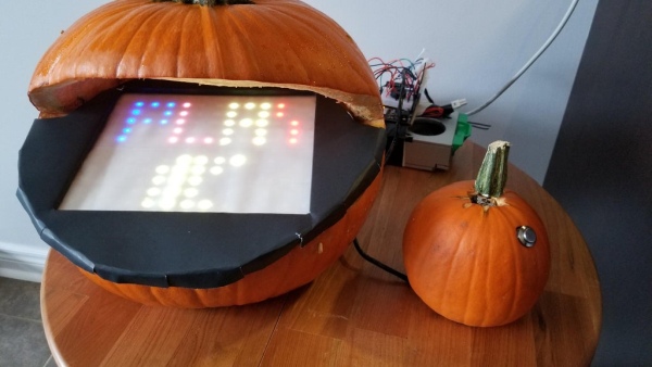
You now have your controller done, your screen done, your power done, your Arduino, and an empty pumpkin.
Using your wooden skewers, stab into your pumpkin to make a platform along the bottom of the pumpkin’s mouth. You’ll want to be able to slide in and out your completed screen to easily lay your screen flat on the bottom of the mouth.
Once you have your platform, feed the LED matrix wires through the bottom of the pumpkin and lay your screen inside.
Outside of your pumpkin you’ll have your power supply and Arduino (In my case I double-sided taped the Arduino to the power supply)
Plug your joystick’s X axis into A0, Y axis to A1, and button to A2, GND to a GND pin on the Arduino, and +5V to the Arduino’s 5V pin.
Attach a piezo speaker to a GND pin and pin 9.
Connect your LED matrix in the same configuration shown in step 2 with the signal pin connected on pin 6.
Connect your Arduino’s VCC pin to a +5V source from the power supply to not have to rely on the USB for power.
Congratulations! Everything is put together, programmed, and, if all went well, should work beautifully. Plug your power supply in and turn it on to start the game.
I hope you were able to follow along and have a great time with this project, Happy Halloween!
Source: Make a Pumpkin Into a Pacman-Playing Game Console!