Summary of Make A Electric Turtle Robot Using Arduino
The article describes the Electric Turtle, a 5" tracked robotic platform designed for Picaxe or Arduino, featuring a sonar/IR ranging mast, I-beam laser-cut construction, and compatibility with Tamiya motors and wheels. It supports multiple battery options, includes servo mounting, and provides cut files, wiring diagrams, and Picaxe code for obstacle avoidance. Laser-cut kits are available and detailed assembly steps, parts, and hardware lists are provided.
Parts used in the Electric Turtle:
- Laser cut parts kit (chassis, decks, mast, risers, etc.)
- 4 × 1.25" #6-32 screws
- 2 × 0.75" #4-40 screws
- 4 × 2" #6-32 screws
- 4 × 0.5" #4-40 screws
- 1 × servo (standard or micro) plus servo hardware pack
- 1 × sonar or IR sensor (PING used in article)
- 1 pair Tamiya 70145 tires
- 1 × Tamiya 70097 motor/gearbox
- 1 × microcontroller (Arduino, Picaxe 28x1, or similar)
- Wires, connectors, heat shrink
- Soldering iron, multimeter, screwdrivers, basic tools
- Spacers and nuts (various, used in assembly)
Be sure to check out my new instructable , the ‘little Tank’! Really nice tracked design complete with cut files!
update: I’ve had so much response on this instructable, thanks to all. If you end up making one, please let me know! I’d love to put your work on my website!
New new update – The Electric Turtle is going to the 2011 Makers Faire in New York with the LMR (lets Make Robots) exhibit!!!
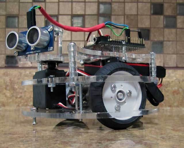
5″ robotic platform, setup for Picaxe or Arduino with sonar ranging mast. This one currently does obstacle avoidance. 90 degree radian etched into the top plate to make turn calibration far easier.
Many battery configurations possible, including lipo (with a regulator) – the deck is spaced to accommodate a large range of power sources.
Designed and made in response to the poorly made/designed commercial offerings – this thing uses I-Beam construction – you can stand on it.
Nice platform to pickup and run with, applicable to many configurations and adaptable to multiple purposes.
Offset ranging mast is provided with cutouts for the ping (what I had on hand), but I put placement holes for several popular models on there as well – tried to make it as universal as possible. Standard IR sensors should fit if you choose to go that route.
Motor configuration is for a Tamiya 70097 motor/gearbox combo – placement holes are in the chassis for either the high or low ratio build configuration of the gearbox. Wheels are Tamiya 70145’s.
Capability to use standard servo or micro servo with adapter plate (included).
Here are laser cut parts kits if you’d rather not cut your own –
Lets make robots! is an excellent resource for DIY robotics as well.
Step 1: Cut your parts
 electric_turtle_7251306.cdr
 electric_turtle_7251306.dxf
 electric_turtle.bas
Step 2: Gather your materials
2. qty 4 1.25″ #6-32 screws (hardware store)
3. qty 2 .75″ #4-40 screws (hardware store)
4. qty 4 2″ #6-32 screws (hardware store)
5. qty 4 .5″ #4-40 screws (hardware store)
6. qty 1 servo (standard or micro, standard recommended) and hardware pack that comes with the servo
7. qty 1 sonar or IR (PING used, others may be substituted)
8. qty 1 pair of Tamiya 70145 tires
9. qty1 Tamiya 70097 motor/gearbox
10. qty 1 Arduino, Picaxe or other microcontroller – this instructable uses the Picaxe 28×1
11. Wires, connectors, heat shrink
If you’d like to keep the soldering to a minimum, just use male-male servo extensions for all of the hookups. This will limit your soldering to the 2 connections on each motor. The motors can also be connected with crimp connectors to eliminate all soldering, but I advise a hard soldered connection to the motors in any case.
Soldering iron, multimeter, screwdrivers, etc…
Standard disclaimer about not cutting your fingers off or sticking a hot iron in your nose..
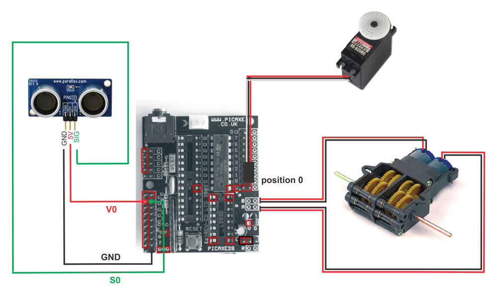
Step 3: Wiring diagram / code for Picaxe
 wiring1.pdf1 MB
Step 4: Assemble your robot!
Step 5: Servo / upper deck
Step 6: Carrier Board / microcontroller
Step 7: Lower deck / servo risers / motor
Attach the motor, risers and wheels as a unit to the lower deck. Use the screws and nuts that came with your motor for this step. Also install the fore / aft anti-tip screws and nuts at this time. Use 2 .5″ screws + nuts.
For more detail: Electric Turtle Robot
- What microcontrollers can be used with the Electric Turtle?
The article mentions Arduino, Picaxe (Picaxe 28x1 used), or other microcontrollers. - Which motor and gearbox does the design use?
The design uses the Tamiya 70097 motor/gearbox combo. - What wheels does the Electric Turtle use?
The platform uses Tamiya 70145 wheels/tires. - Can I use a LiPo battery with the Electric Turtle?
Yes, many battery configurations are possible including LiPo if used with a regulator. - Does the project include wiring diagrams and code?
Yes, the instructable provides a wiring diagram and electric_turtle.bas Picaxe code for obstacle avoidance. - Are laser cut part files provided?
Yes, CDR and DXF cut files are provided and laser cut parts kits are available. - Is the sonar mast compatible with different sensors?
Yes, the offset mast has cutouts for the PING and placement holes for several popular models and standard IR sensors should fit. - What screw sizes are needed for assembly?
The parts list specifies 1.25" #6-32, 2" #6-32, 0.75" #4-40, and 0.5" #4-40 screws among others.