Water is a precious resource. Millions of people do not have access to clean drinking water, and as many as 4000 children die from water contaminated illnesses every day. Yet, we continue to be wasteful with our resources. The overarching goal of this project is to motivate more sustainable water use behavior and raise awareness about global water issues.
This is an instructible on how to crudely detect water flow in a pipe and drive an ambient display. I am using a piezo transducer, some LED’s and an arduino. The device is a rough prototype of what will eventually become a persuasive technology that motivates sustainable behavior and raises awareness about water use.
This is a project by Stacey Kuznetsov and Eric Paulos at the Living Environments Lab, at Carnegie Mellon University Human Computer Interaction Institute.
Produced by
Stacey Kuznetsov
[email protected]
http://staceyk.org
Eric Paulos
[email protected]
http://www.paulos.net/
Living Environments Lab
http://www.living-environments.net
The video below illustrates a previous version of this project, where a microphone is used instead of a piezo element to detect water flow. You will achieve better performance when using a piezo transducer, so this instructible details the piezo approach.
Special thanks to Briam Lim, Bryan Pendleton, Chris Harrison and Stuart Anderson for help with ideas and design of this project!
Step 1: Gather Materials
You will need:
– Breadboard
– Microcontroller (I used an Arduino)
– Mastic
– Piezo Transducer (http://www.radioshack.com/product/index.jsp?productId=2062402)
– A few LED’s (I used 2 yellow, 2 red, 2 green)
– Candle holder or similar-sized container
– Wire
– 1 Mohm (or other large value) resistor
– 4.7K Resistors (3)
– 1K Resistors (1)
– Low-value Resistors (for the LED’s)
– Clipping Wires
– Jumper Wires
– Mastic- op amp (LM613)
Step 2: Build the Circuit
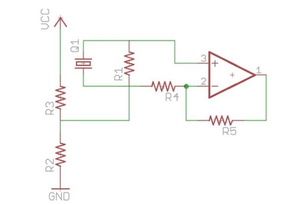
he circuit consists of an amplifier to increase the signal from the piezo and a voltage divider to lift the base voltage.
There is a high-value resistor between the two inputs form the piezo, which acts as a pull-down resistor for the signal.
Step 3: Test the Circuit
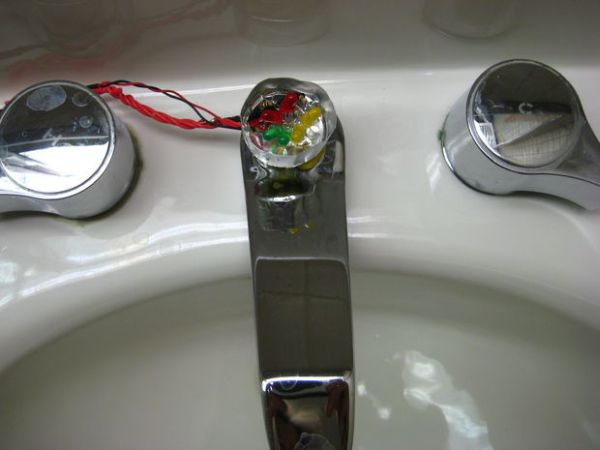
Attach the piezo to the circuit, and hook up the arduino.
The voltage divider sets the base voltage at 2.5V, so the base readings for the signal should be around 512 on the Arduino analog pin (half way between 0 and 1023). Mine fluctuates +/-30 around 520. You may see some fluctuation around this number.
For more detail: Low Cost Water Flow Sensor and Ambient Display