
Summary of How to Drive a 7 Segment LED Display with an Arduino
This article explains how to drive a single common cathode 7-segment LED display using an Arduino microcontroller. It details the hardware components required, including resistors and jumper wires, and provides specific binary codes for displaying numerals 0-9 by controlling individual segments (a-g and the decimal point). The guide covers pinout variations, wiring diagrams, and emphasizes verifying connections via datasheets or testing to ensure correct operation.
Parts used in the Drive a 7 Segment LED Display with an Arduino:
- Common Cathode 7 Segment LED Display
- Arduino
- 8 270Ω Resistors
- Jumper Wires
In this project, we will show how to drive a single 7 segment LED display with an arduino microcontroller.
A 7 Segment LED Display is an electronic device housing 8 individual LEDs.
Using this device, we can display all numerals and many alphabetical characters and many more types of symbols. The 7 segment LED is really a versatile display device.
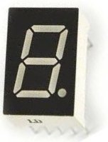
For this project, we will write a program that uploads to an arduino board that will display the numerals 0-9.
The output is produced by turning on combinations of segments that represent the various numerals 0-9.
Components Needed
- Common Cathode 7 Segment LED Display
- Arduino
- 8 270Ω Resistors
- Jumper Wires
The 270Ω resistors attach to the 8 digital output pins connected to the 8 segments of the LED display. They limit current going to the individual LEDs, so that they don’t get burnt out from too much power.
To understand how this program works, let’s first look at the makeup of a 7 segment LED display.
The LED display, again, is made up of 8 individual LEDs, as shown above. The LEDs go in order of the alphabetical characters which you see. From first to last, the LEDs from 1-8 are a, b, c, d, e, f, g.
The decimal point would be the last pin.
To create a 0, we would have to light LEDs a,b,c,d,e,f. This would give us a zero. g would be left unlit. Thus, to create a 0 in code, it would be represented by B11111100.
To create a 1, we would have to light LEDs, b,c. All other LED would be left unlit. Thus, to create a 1 in code, it would be represented by B11000000.
To create a 2, we would have to light LEDs a,b,d,e,g. Thus, to create a 2 in code, it would be represented by B11011010.
To create a 3, we would have to light LEDs a,b,c,d,g. Thus, to create a 3 in code, it would be represented by B11110010.
To create a 4, we would have to light LEDs b,c,f,g. Thus, to create a 4 in code, it would be represented by B01100110.
To create a 5, we would have to light LEDS a,c,d,f,g. Thus, to create a 5 in code, it would be represented by B10110110.
To create a 6, we would have to light LEDs a,c,d,e,f,g. Thus, to create a 6 in code, it would be represented by B10111110.
To create a 7, we would have to light LEDs, a,b,c. Thus, to create a 7 in code, it would be represented by B11100000.
To create an 8, we would have to light LEDs a,b,c,d,e,f,g. Thus, to create an 8 in code, it would be represented by B11111110.
To create a 9, we would have to light LEDs, a,b,c,f,g. Thus, to create a 9 in code, it would be represented by B11100110.
So now that you know how each numeral can be shown by deciding which LEDs to turn on, let’s see how we will wire the 7 segment LED display to the arduino.
Before we can do that, we must know the pinout of the 7 segment LED display. In our circuit, we will use a common cathode LED display. This is a 7 segment LED display in which all grounds of the LEDs are tied together.
The pinout of the common cathode LED display is shown below.
Common Cathode 7 Segment LED Display Pinout
These are the 2 pinout diagrams of the common cathode 7 segment LED display. Some have the pins on the sides (laterally). Others have the pins on the top and bottom. Thus, we show both pinout diagrams.
You will need this to know how to hook up the display to the arduino board.
Note– Even though many different types of 7 segment LED displays follow the above schematics, it is not guaranteed. The best way to know the connections is to obtain the datasheet for the LED display in use or to buzz it out by connecting power to each of the pins to see which lights up. If you don’t get the connections right, the circuit will not produce the output of showing numerals 0-9. So it is very important to know which pins are which.
Circuit Schematic
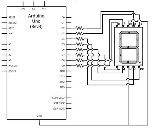
The schematic for the 7 segment LED display connected to the arduino is shown below.
For more detail: How to Drive a 7 Segment LED Display with an Arduino
- What is a 7 Segment LED Display?
An electronic device housing 8 individual LEDs that can display numerals, alphabetical characters, and symbols. - How do you create the numeral 0 on the display?
Light LEDs a, b, c, d, e, f while leaving g unlit, represented by the code B11111100. - Why are 270Ω resistors used in this project?
They attach to digital output pins to limit current and prevent the individual LEDs from burning out. - Does the pinout of a 7 segment LED display vary?
Yes, some have pins on the sides while others have them on the top and bottom, so checking the datasheet is important. - What happens if the connections are not made correctly?
The circuit will not produce the output of showing numerals 0-9. - How can you verify the correct pin connections?
You can obtain the datasheet for the LED display or buzz it out by connecting power to each pin to see which lights up. - What type of LED display is used in this specific circuit?
A common cathode LED display where all grounds of the LEDs are tied together. - Can this project display letters as well as numbers?
Yes, the device can display many alphabetical characters and other types of symbols.
