I designed this project for a 10-hour workshop for ChickTech.org whose goal is to introduce teenage women to STEM topics. The goals for this project were:
- Easy to build.
- Easy to program.
- Did something interesting.
- Low-cost so participants could take it home and continue to learn.
With those goals in mind, here were a couple of the design choices:
- Arduino compatible for ease of programming.
- 4xAA battery power for cost and availability.
- Stepper motors for accurate motion.
- 3D Printed for ease of customization.
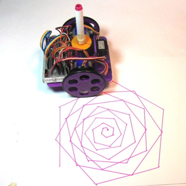
- Pen plotting with Turtle graphics for interesting output.
- Open Source so you could make one of your own!
Here is the robot that came closest to what I wanted to do: http://mirobot.io. I don’t have a laser cutter and shipping from England was prohibitive. I do have a 3D printer, so I guess you can see where this is going . . .
Don’t let the lack of a 3D printer deter you. You can locate local hobbyists willing to help you out at https://www.3dhubs.com/.
This project is licenced under Creative Commons, and utilizes 3D parts based on designs by others (as indicated in the next section), the most restrictive of which is the wheel, which is Non-Commercial. That means this project must also be Non-Commercial. Don’t be this guy.
Step 1: Parts
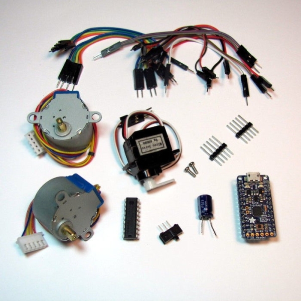
There are a number of ways to power, drive, and control robots. You may have different parts on hand that will work, but these are the ones I’ve tried and found to work well:
Electronics:
- 1- *Adafruit Pro Trinket 3V- adafruit.com/products/2010
- Hardware under CC BY-SA licence
- Software (Bootloader) under GPL licence
- 2- Geared 5V Stepper- adafruit.com/products/858
- 1- ULN2803 Darlington Driver – adafruit.com/products/970
- 1- Half-size breadboard- adafruit.com/products/64
- 16- Male-male jumpers- adafruit.com/products/759
- 1- Micro servo- adafruit.com/products/169
- 1 – SPDT slide switch – adafruit.com/product/805 or www.digikey.com/product-detail/en/EG1218/EG1903-ND/101726
- 1- Male pin header- digikey.com/short/t93cbd
- 2- 2 x AA Holder- digikey.com/short/tz5bd1
- 1- USB micro cable
- 4- AA Batteries
*Note: See the last step for a discussion on using regular Arduino or Raspberry Pi boards.
Hardware:
- 2- 1 7/8″ ID x 1/8″ O-ring- mcmaster.com/#9452K96
- 1- Caster 5/8″ bearing- mcmaster.com/#96455k58/=yskbki
- 10- M3 x 8mm pan head screw- mcmaster.com/#92005a118/=z80pbr
- 4- M3 x 6mm flat head screw- mcmaster.com/#91420a116/=yskru0
- 12- M3 Nut- mcmaster.com/#90591a250/=yskc6u
3D-Printed Parts (check out www.3dhubs.com if you don’t have access to a printer):
- 1 x Ball bearing caster – thingiverse.com/thing:1052674 (based on work by onebytegone, CC BY-SA 3.0)
- 1 x Chassis – thingiverse.com/thing:1053269 (original work by Maker’s Box, CC BY-SA 3.0)
- 2 x Wheels – thingiverse.com/thing:862438 (based on work by Mark Benson, CC BY-NC 3.0*)
- 2 x Stepper bracket – thingiverse.com/thing:1053267 (based on work by jbeale, CC BY-SA 3.0)
- 1 x Pen Holder / servo bracket – thingiverse.com/thing:1052725 (original work by Maker’s Box, CC BY-SA 3.0)
- 1 x Pen Collar – thingiverse.com/thing:1053273 (original work by Maker’s Box, CC BY-SA 3.0)
* Note: CC BY-NC is a non-commercial licence
Tools and Supplies:
- Phillips screw driver
- Hot glue gun
- Digital multi-meter
- Sharp knife
- Crayola colored markers
Step 2: Flash the Firmware
Before we get too far into construction, lets load the test firmware on to the microcontroller. The test program just draws for boxes so we can check for proper direction and dimension.
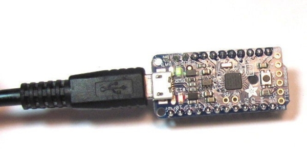
To talk to the Trinket Pro, you are going to need:
- Driver from https://learn.adafruit.com/introducing-pro-trinket…
- Arduino software from https://learn.adafruit.com/introducing-pro-trinket…
Lady Ada and the Adafruit team have created a far better set of instructions in the links above than I can provide. Please use them if you are stuck.
Note: The one trick that makes the Trinket different from regular Arduino is that you have to reset the board before uploading the sketch.
Step 3: Pen Holder and Battery Holders
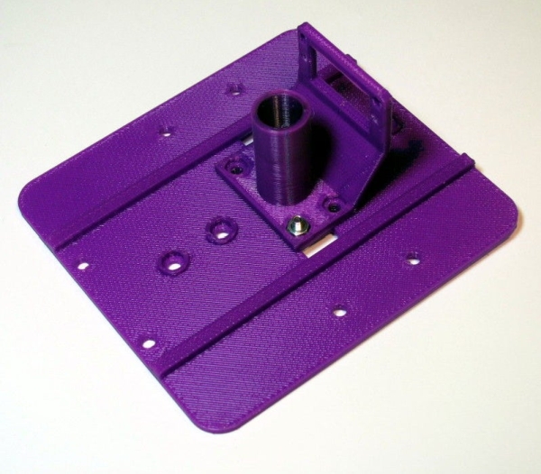
- Install the Pen Holder with the Servo Bracket on the shorter side of the chassis (Image 1).
- Insert the nuts on the top side of the chassis (Image 2)
- Attach the battery holders on the bottom of the chassis using 3Mx6mm flat-head screws (Images 3 & 4).
- Thread the battery leads through the rectangular cable runs (Image 4 & 5).
- Repeat for the other battery holder.
Note: Unless specified, the remainder of the screws are 3Mx8mm pan head srews.
Step 4: Wheels
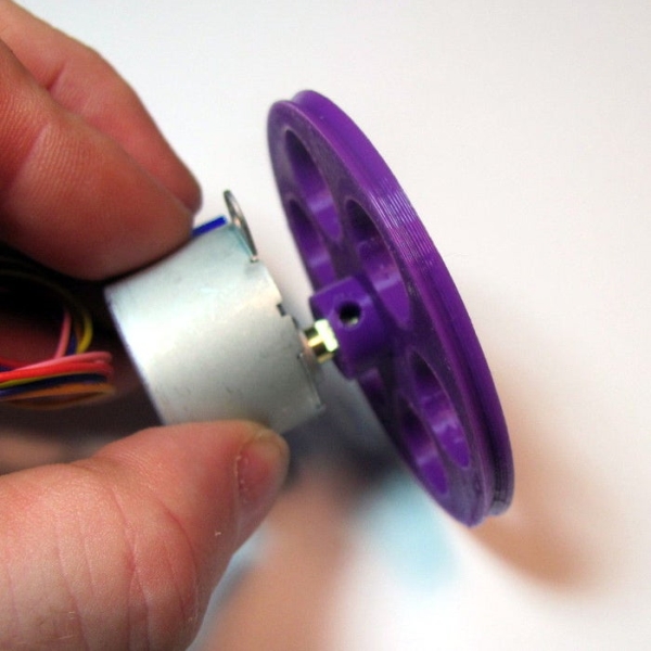
- Test fit your wheel to the stepper shaft (Image 1).
- If it is too tight, you can heat the wheel hub with a hair drier or hot air gun and then insert the shaft.
- If it is too loose, you can use a 3Mx8mm screw to hold it against the flat of the shaft (Image 2).
- If you are a perfectionist, you can calibrate your printer and get it just right.
- Place the o-ring around the rim of the wheel (Image 3 & 4).
- Repeat for the other wheel.
Step 5: Stepper Backets
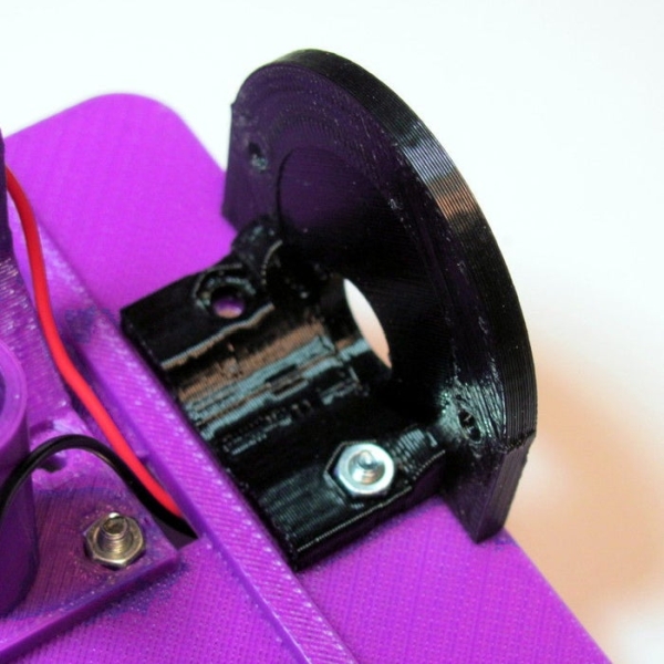
- Insert a nut into the stepper bracket and attach them to the top of the chassis with a screw (Image 1).
- Insert the stepper into the bracket and attach with screws and nuts.
- Repeat for the other bracket.
Step 6: Caster
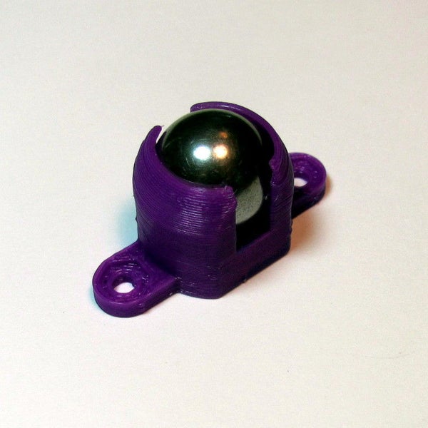
- Insert the ball bearing into the caster.
- Do not force it in or it will break. Use a hair-drier or hot air gun to soften the material if needed.
- Attach the caster to the bottom side of the chassis in front of the battery holder.
Read more: Low-Cost, Arduino-Compatible Drawing Robot