Summary of Line Following Robot using arduino
This project builds a line-following robot using an Arduino, two light sensors (a photoresistor and a GA1A12S202 analog light sensor), an LED indicator, and two servo-driven wheels on a Parallax BOEBot base. Sensors detect reflected light differences between black and white surfaces to steer the servos left or right. Components are mounted on a breadboard taped to the robot base, wired to the Arduino via a motor shield, and powered by a battery pack. The LED indicates power and aids sensor reflection.
Parts used in the Line Following Robot:
- Arduino
- Motor Shield (Adafruit product 1438)
- LED with 100 ohm resistor
- Photo cell (photoresistor) with 1K ohm resistor (Adafruit product 161)
- GA1A12S202 Log-scale Analog Light Sensor (Adafruit product 1384)
- Parallax BOEBot Robot for Arduino Kit base with two servo-driven wheels (Adafruit product 749)
- Breadboard
- Battery with battery holder
- Black marker or black tape and white paper
- Tape to mount and organize parts
- Wires and jumper wires
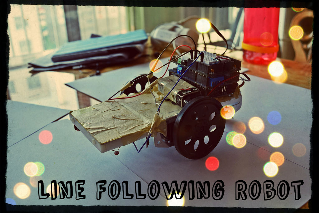
This is a Line Following Robot. It follows a black line that is drawn. It is able to detect the black line through one photocell and one analog light sensor. There is an LED in between the two sensors that gives off red light when the Arduino is powered on. Then, when the light is reflected back, more light is detected when it is reflected on the white surface, compared to when it is reflected on the black surface. Using this, the right and left servo motors move accordingly to turn left or right when the sensors detect white surface rather than black. I used the Parallax BOEBot Robot for Arduino Kit as my base for the robot. Then I placed a breadboard in front of the base to attach all the sensors with the LED to face the black line.
Follow these steps, and you will be able to build your own line following robot! 🙂
Step 1: Step 1: Parts
Parts needed:
- Arduino
- Motor Shield (https://www.adafruit.com/products/1438)
- LED with 100 ohms resistor
- Photo cell with 1K ohms resistor (https://www.adafruit.com/products/161)
- GA1A12S202 Log-scale Analog Light Sensor (https://www.adafruit.com/products/1384)
- A base for the robot with 2 wheels attached to servo motors ** I used : Parallax BOEBot Robot for Arduino Kit (https://www.adafruit.com/products/749)
- A breadboard
- A battery with a battery holder
- Black marker or black tape with white papers
- Tape to tape all the parts together
- Wire to connect all the parts (also jumper wires)
Step 2: Step 2: Assemble 1
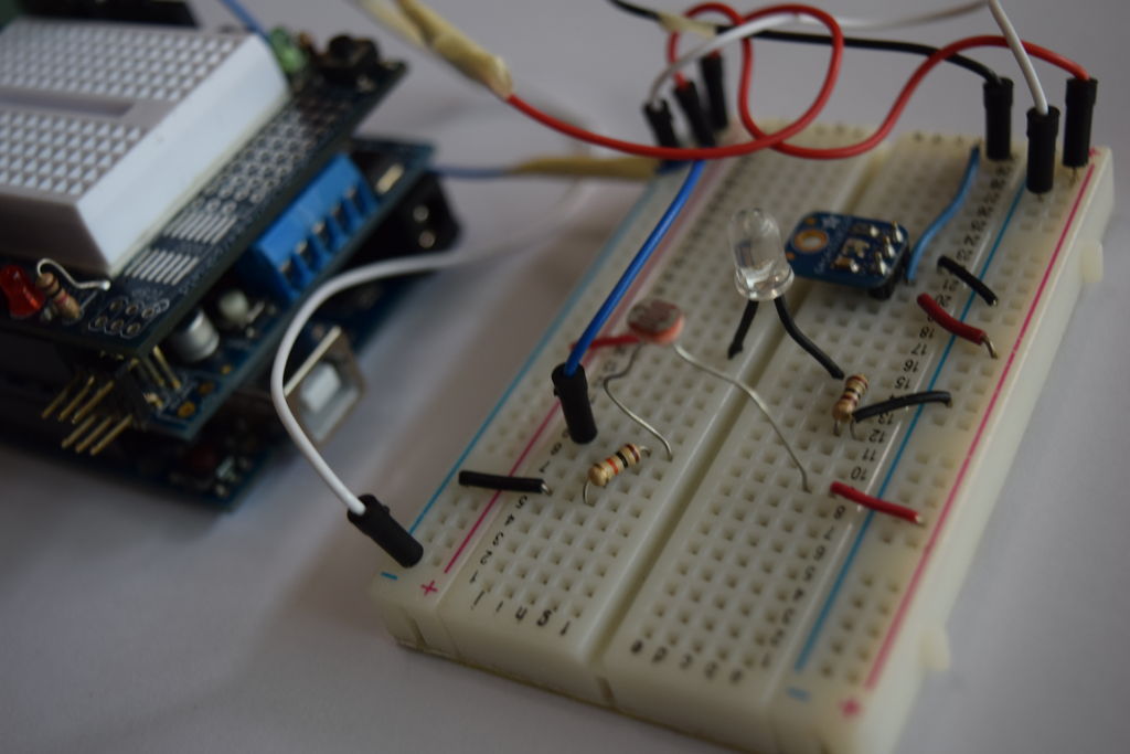
First, hook up all the sensors!
Connect the photo cell. One end should go to power and the other should connect to the 1K ohms resistor. Then, on the side with the photo cell and the resistor, connect to the analog pin. Next, connect the other end of the resistor to ground. Then connect the LED with the 100 ohm resistor on the breadboard. Finally connect the light sensor to the breadboard according to the label: ground, power, and one analog pin. Then connect all the wires with jumper wires to the Arduino. Make sure that your jumper wires are long enough to reach the Arduino on the base of the robot.
Second, attach the breadboard to the base of the robot.
I used tape since I couldn’t really think of anything else, but you can use anything if it is going to be able to attach the breadboard (facing down) to the robot. Then, use more tape to organize the jumper wires.
For more detail: Line Following Robot using arduino
- What sensors are used to detect the line?
A photo cell (photoresistor) and a GA1A12S202 analog light sensor are used. - How does the robot distinguish black from white surfaces?
The sensors detect reflected light; more light is reflected from white surfaces than from black, and the Arduino uses that difference to steer. - What indicates the Arduino is powered on?
An LED placed between the two sensors gives off red light when the Arduino is powered on. - How are the servos controlled to turn left or right?
The Arduino reads the analog sensors and moves the right and left servo motors accordingly to turn toward the detected black line. - What robot base was used in this project?
The Parallax BOEBot Robot for Arduino Kit base with two wheels attached to servo motors was used. - How are the sensors and LED mounted to the robot?
They are placed on a breadboard taped to the front of the robot base with the LED and sensors facing the line. - What resistors are required for the sensors and LED?
A 1K ohm resistor is used with the photo cell and a 100 ohm resistor is used with the LED. - What power source is used for the robot?
A battery with a battery holder is used to power the robot.