Summary of AC Dimmer Circuit
This project is a simple AC dimmer for incandescent bulbs providing 128 brightness levels by chopping the AC waveform. An Arduino provides dimming and zero-cross signals; an H11AA1 detects zero crossings, a MOC3020 drives a BTA12-600 triac to switch AC to the bulb, and the onboard LED mirrors bulb dimming. PCB files, schematic, and example Arduino code (including potentiometer control and fades) are provided to build the circuit.
Parts used in the AC Dimmer:
- 33K resistor
- 10K resistor
- 1K resistor
- 470 ohm resistor
- 180 ohm resistor
- 2.4K resistor
- 0.01uF capacitor
- generic LED
- H11AA1 optocoupler AC input 1 channel
- MOC3020 DIP-6 optoisolator triac driver
- BTA12-600 snubberless TRIAC (600 V, 12 A)
- Arduino (for control signals)
- AC power plug and lamp cord (Hot and Neutral conductors)
- PCB and screw terminals
Overview
Simple AC Dimmer circuit for incandescent bulbs. 128 levels of brightness. Parts are relatively cheap!
How it Works
- This is an AC Chopping Circuit.
- The dim level sets where the AC waveform gets chopped on. More of the cycle makes the bulb brighter, less is dimmer.
- (from digikey http://www.digikey.com/ca/en/techzone/lighting/resources/articles/Retrofit-LED-Bulbs-and-Drivers.html)
Photo
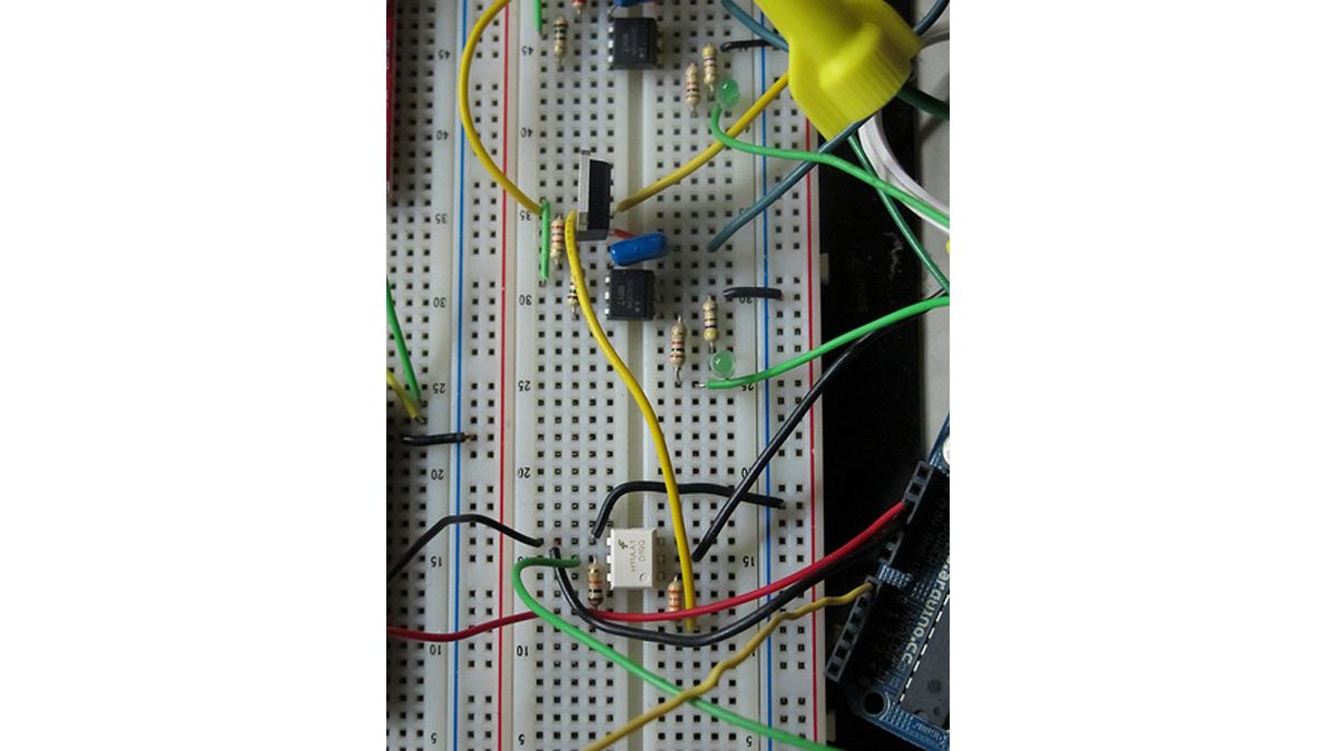 |
- Digital Signals. The four signals on the left. They are labelled on the board.
- Yellow: light dimming signal, comes from Arduino digital pin 11.
- White: zero-cross signal, goes to Arduino digital pin 2 in.
- Red: arduino +5V supply.
- Black: arduino GND.
- The LED on board should dim or fade along with the AC light source. Fading will not work until AC power is connected, it depends on the zero-cross info from the H11AA1 chip.
- AC Signals. The four white cords on the right. The bottom two cables on the right are the AC plug. The top two are the Bulb. These are labelled on the board, but are partially covered by the large screw terminals.
- Bottom is AC Power – Neutral.
- Bottom Middle is AC Power – Hot.
- Top Middle is Bulb – Hot.
- Top is Bulb – Neutral.
- NOTE: For help identifying Hot and Neutral on lamp cord, look here.
Code
- example with slow on/off fade:
- example with potentiometer control:
Schematic
 |
Board Layout
PCB Files
- EagleCAD –
- Gerber –
Building the Circuit
Parts
- 33K
- 10K
- 1K
- 470
- 180
- 2.4K
- 0.01uF capacitor
- generic LED
- H11AA1 – Optocoupler AC Input 1 Channel http://www.jameco.com/webapp/wcs/stores/servlet/Product_10001_10001_18825_-1
- MOC3020 – DIP-6 OPTOISOLATOR Triac Driver http://www.jameco.com/webapp/wcs/stores/servlet/Product_10001_10001_277780_-1
- BTA12-600 – 600 V, 12 A, SNUBBERLESS TRIAC http://www.jameco.com/webapp/wcs/stores/servlet/Product_10001_10001_2034010_-1
From a PCB
If you had some of these manufactured, then you’ll want to build the PCB. See our tutorial on Populating a Fabricated PCB.
For more detail: AC Dimmer Circuit
- How does the dimmer control bulb brightness?
The dimmer chops the AC waveform so changing where the cycle is cut controls brightness; more of the cycle makes the bulb brighter. - What role does the H11AA1 play?
The H11AA1 provides zero-cross information to the Arduino so fading syncs with AC and depends on that input. - How does the Arduino connect to the dimmer board?
Arduino digital pin 11 provides the dimming signal, digital pin 2 receives the zero-cross signal, plus 5V and GND connect to red and black wires respectively. - Which components switch the AC to the bulb?
The MOC3020 optoisolator drives the BTA12-600 TRIAC, which switches the AC to the bulb. - Does the onboard LED reflect bulb dimming?
Yes, the onboard LED should dim or fade along with the AC light source and requires the zero-cross input to work. - What files are provided for building the PCB?
The project provides EagleCAD PCB files and Gerber files. - Can I control dimming with a potentiometer?
Yes, example code for potentiometer control is provided in the project. - How many dimming levels does the circuit support?
The dimmer provides 128 levels of brightness.