Summary of LilyPad Arduino Sensor Demo Mat
This tutorial guides building a LilyPad Arduino sensor demo mat to experiment with and showcase multiple sensors without repeatedly uploading code. It covers required supplies, arranging sensors, drawing and finalizing circuit lines on fabric, removing temporary markings, and stitching components in place for a durable, demonstrable e-textile project.
Parts used in the LilyPad Arduino Sensor Demo Mat:
- 1 x LilyPad 328 Main Board
- 1 x ProtoSnap - LilyPad Development Board (includes components listed below)
- 1 x LilyPad Simple Board
- 1 x LilyPad Button
- 1 x LilyPad Slide Switch
- 5 x LilyPad White LED
- 1 x LilyPad RGB tri-color LED
- 1 x LilyPad Light Sensor
- 1 x LilyPad Temp Sensor
- 1 x LilyPad Buzzer
- 1 x LilyPad Vibe board
- 1 x LilyPad FTDI Basic
- 2 x Conductive Thread Bobbin
- 1 x Needle Set
- 7 x sewable snaps
- 1 x Piece of fabric large enough to hold all sensors
- 1 x Fabric marking pen (Dritz Mark B Gone used)
This tutorial shows you how to create a sensor demo mat for the LilyPad Arduino. I wanted a place where I could experiment with the different sensors, but also something that I could use to show examples of what can be done without constantly uploading code.
Step 1: Step 1: Supplies
To complete this project I used the following:
- 1 x LilyPad 328 Main Board
- 1 x ProtoSnap – LilyPad Development Board which includes the following:
- 1 x LilyPad Simple Board
- 1 x LilyPad Button
- 1 x LilyPad Slide Switch
- 5 x LilyPad White LED
- 1 x LilyPad RGB tri-color LED
- 1 x LilyPad Light Sensor
- 1 x LilyPad Temp Sensor
- 1 x LilyPad Buzzer
- 1 x LilyPad Vibe board
- 1 x LilyPad FTDI Basic
- 2 x Conductive Thread Bobbin
- 1 x Needle Set
- 7 x sewable snaps
- 1 x Piece of fabric big enough to hold all of the sensors
- 1 x Fabric Marking pen (I used a Dritz Mark B Gone marking pen which can be found online, at many craft stores, or even stores like Wal-mart)
Although I had the LilyPad Development Board, I decided to use the LilyPad SImple Board so I could use the extra pins as switches.
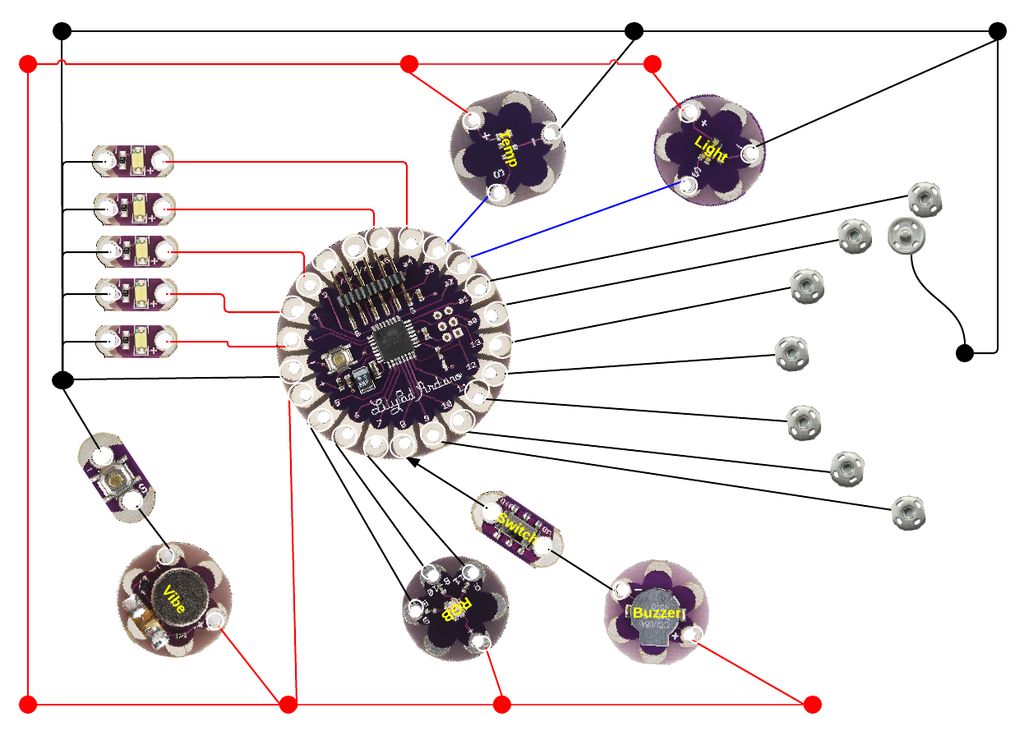
Step 2: Step 2: The Circuit Diagram
Before beginning any project it is good to take the time to think everything through. I put images of the different sensors and components into lucidchart.com and played around with the placement of the sensors to find an arrangement that wouldn’t just work, but one I also found to be aesthetically pleasing.
Step 3: Step 2: Sensor Placement
Based on the diagram, I arranged all of the sensors and switches onto the fabric. I used the marking pen to indicate where each pin and component would be placed. A dot inside the pin hole was enough to let me know where each component would go.
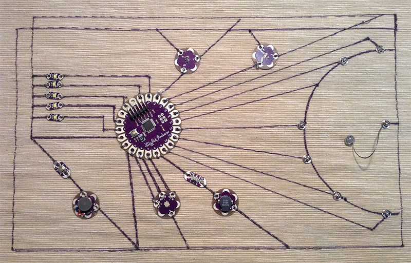
Step 4: Step 4: Draw the Circuits
I removed the sensors and used the marking pen to draw the circuit onto the fabric. I used a ruler to make sure all of my lines were straight. The nice thing about a pen like a Dritz Mark B Gone is that the ink disappears when it gets wet which allows you to erase your lines with a damp rag if you need to make changes.
When I had the lines drawn, I again placed the sensors on the mat to make sure that everything lined up the way I wanted it to. I ended up changing the position of the RGB light slightly so the lines were less likely to make contact with the other pins on the LilyPad.
I wanted the lines to be part of the final piece so, once I was satisfied with the diagram, I traced the lines with a permanent marker. If I did it over, I would probably color code the lines so that it can be better used to explain how the circuit works.
Step 5: Step 5: Clean off the Marking Pen
I soaked the fabric in water and then let it dry overnight to remove the blue marking pen marks from the fabric before I started sewing.
Step 6: Step 6: Stitch on the Sensors and Other Components (optional)
To ensure that the sensors stayed put while I sewed the circuits, I did a quick stitch with plain thread to hold the components in place.
For more detail: LilyPad Arduino Sensor Demo Mat
- What is the purpose of the sensor demo mat?
To experiment with different LilyPad sensors and show examples without constantly uploading code. - Which LilyPad main board was used?
A LilyPad 328 Main Board was used. - Why was the LilyPad Simple Board chosen over the Development Board?
The Simple Board was used to free up extra pins to use as switches. - How were sensor placements planned?
Sensor images were arranged in lucidchart.com to experiment with placements before marking the fabric. - How were circuit lines drawn on the fabric?
Lines were drawn with a fabric marking pen using a ruler, then traced with a permanent marker once finalized. - How were temporary marking pen lines removed?
The fabric was soaked in water and left to dry overnight to remove the Dritz Mark B Gone marks. - How were components secured before sewing?
A quick stitch with plain thread was used to hold components in place while sewing the circuits. - Was any color coding used for circuit lines?
No; the author traced lines with a permanent marker but noted they would color code if doing it over.