Summary of Creative diorama lighting with the Arduino and TLC5940
Summary (under 100 words): This article shows how to add realistic, scripted lighting to model railroad buildings using an Arduino and TLC5940 LED drivers. It covers necessary tools, parts, building and masking techniques to prevent light bleed, and controller architecture. The Arduino code organizes LEDs into clusters (RGB and white), uses precalculated sine-wave color patterns for RGBs, and schedules on/off times per LED for realistic variability. Practical tips on brightness, testing, and assembly are included.
Parts used in the Arduino and TLC5940 Model Building Lighting Project:
- microtivity IL336 4.8mm Wide Angle White Straw Hat LED w/ Resistors (Pack of 100)
- microtivity IL614 5mm Diffused RGB Controllable LED, Common Anode (Kit, Pack of 30)
- microtivity IM414 Double-sided Prototyping Board (4x6cm, Pack of 5)
- POW3U PowerBoard-3U with Power Rails, 1 Sided PCB, 3.94 x 6.30 in
- Various male-to-male, male-to-female, and female-to-female jumper wires (Dupont connectors)
- TLC5940NT (2 or more)
- 10 uF 25V radial capacitors
- 10K ohm 5% 1/4W resistors
- 2K ohm 5% 1/4W resistors
- 0.1 uF 25V capacitors
- 16 pin female IDC sockets
- 16 pin male header with shroud (straight)
- 16-conductor rainbow ribbon cable (28AWG)
- Large solderless breadboard (WBU-208-R)
- Small solderless breadboards with power bus (WBU-301-R)
- 40 position unshrouded header 2.54mm (single row snappable)
- Thick white paper or cardboard (for LED wrappers/boxes)
- Common white glue
- Evergreen Scale Models channel (5/16" or similar)
- Foam sheets for masking and light control
- Model buildings or structures (or LEGO)
- Arduino Uno R3
I became interested in model railroading a few years ago. It’s a hobby that requires skills in precision painting, model building, scenery design, wood working, electrical engineering and about a dozen other skills that I’m forgetting right now. It is an excellent creative outlet.
Realism can be a part of the hobby, like laying out a train line complete with all the scenery with historical accuracy. You can also choose to just build a fantasy land complete with cities, realistic grass, unicorns and Godzilla-like monsters fighting Transformers for rule over the land. Regardless, you will be assembling and painting a variety of buildings to enhance the world you are creating.
I’m writing about adding some realism to the town: lighting. You can light a building by just plugging in a bunch of little model light bulbs and light everything in a uniform way. Towns don’t work like that though. People move from room to room, lights go on and off, street lights flicker, restaurants change the lighting through the night.
We’re going to look at how to use an Arduino, a few TLC5940’s and diorama skills to script the LEDs of a part of a town to create realistic lighting.
Step 1: Tools
This looks like a long and expensive list of tools. You may have many of these tools already or those that can do the job just as easily.
Tools you’ll need:
- A hammar
- A small nail
- A multimeter
- Needle nose pliers
- Calipers like Neiko 01407A Stanless Steel 6-Inch Digital Caliper with Extra-Large LCD Screen and Instant SAE-Metric Conversion or be really good with a ruler.
- A model file set, such as Tamiya Basic File Set or a tool to make very fine notches. Wire cutters work but easier to make a mistake. Modelers probably already have something like this.
- Wire strippers. I use these: Irwin Industrial Tools 2078300 8-Inch Self-Adjusting Wire Stripper with ProTouch Grips Note: The description says it is good to 24 AWG, but it works well down to 28 AWG stranded.
- Wire cutters similar to Xuron 170-II Micro-Shear Flush Cutter as you will want something with a small nose.
- Soldering iron with temperature control
- Ventilation
- Table top vices like these:
- PanaVise Model 201 “Junior” Miniature Vise
- PanaVise 301 Standard PanaVise
- PanaVise 209 Vacuum Base Pv Jr. Note: I regret this and would rather have 2 of the model 201’s. The vacuum base is not great on wood and it doesn’t have the weight to keep it steady.
Optional:
- A decade box when you need that one odd resistor that you don’t have on hand: Elenco 1% 1 Watt Resistor Substitution Box
- An oscilloscope.
- A circuit board holder such as: PanaVise 315 Circuit Board Holder You can remove the vice in the 301 and replace it with the board holder. You need a vice to crimp a few ribbon cables.
- Helping hands or something similar.
- Bamboo skewers.
Step 2: Parts
Some of these parts are optional and you have alternatives. I used three retailers: Amazon, Mouser and Jameco. All three delivered within 2 days thanks to Amazon Prime, Priority Mail and really fast customer fulfillment.
The list is ordered by who fullfilled my order:
Amazon:
- microtivity IL336 4.8mm Wide Angle White Straw Hat LED w/ Resistors (Pack of 100)
- microtivity IL614 5mm Diffused RGB Controllable LED, Common Anode (Kit, Pack of 30)
- microtivity IM414 Double-sided Prototyping Board (4x6cm, Pack of 5)
- POW3U PowerBoard-3U with Power Rails, 1 Sided PCB, 3.94 x 6.30 in (100 x 160 mm)
- A lot of male to male, male to female and female to female jumper wires. The Dupont connectors were the best since they are square and can mash up against each other.
A note on Microtivity: Every part worked fine. The straw hats have a very wide angle and are great for building lighting. The RGB and white both draw 20mA according to their data sheets and that made it much easier to share the TLC5940’s with both types. My regret was that I went with the prototyping board instead of a solder breadboard or strip board because of the time spent soldering bridges and buses. You will improve your soldering skills though.
Mouser:
- 2 or more TLC5940NT
- 10 10uF 25v radial caps cut tape
- 10 10K ohm 5% 1/4w resistor PN 660-CF1/4CT52R103J cut tape
- 10 2k OHM 5% 1/4w resistor PN 660-CFS1/4CT52r2027 cut tape
Note: The 2K resistor is based on a formula in the TLC5940NT’s data sheet
Jameco:
- 10 .1uF 25v cap 20% PN 151116
- Several 16 pin female IDC sockets PN 119467.
- Several 16 pin male header w/shroud straight PN 68180 mates with the above 16 pin female connector.
- 1 Cable Ribbon 16 Conductor Rainbow 28AWG 10 Feet Flat PN 28RC16-10VP
- A large solderless breadboard such as PN WBU-208-R
- A couple small breadboards such as PN WBU-301-R with power bus
- Several Connector Unshrouded Header 40 Position 2.54mm Solder Straight Thru-Hole PN 7000-1X40SG-R
Part 7 is just a 40 pin single row snappable header. You will need 64 pins per node board, which I’ll describe in future step. You’ll need two 40 pin headers per node board. Also, it is easy to miscount the number of pins you need when snapping them off so get a couple of extra headers for mistakes.
Note: Some of the parts above say “have 10 of this or that.” Some vendors have minimum orders or parts like resistors and capacitors.
Other stuff:
- Thick white paper or cardboard that can hold a little weight.
- Common white glue
- Evergreen Scale Models: Channel 5/16″ (7.9mm) PN 268 or something similar.
- Various other parts to make your diorama look realistic.
- Model buildings or similar structures, like lego.
- Foam sheets, see picture. You can find them in most kid’s craft stores.
- An Arduino Uno R3
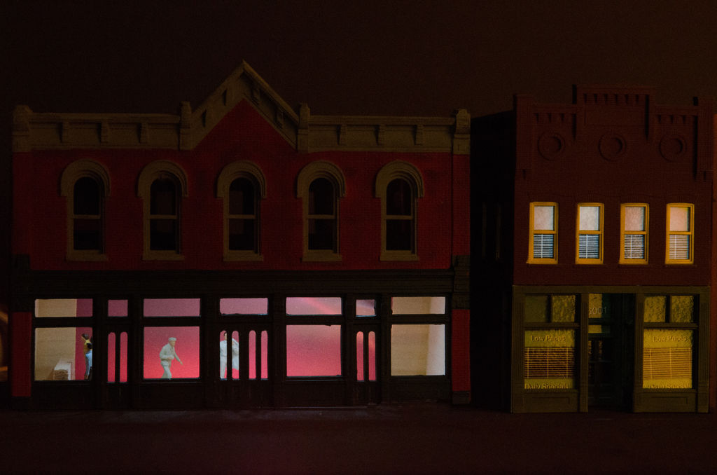
Step 3: Overview of lighting the buildings
The above ground setup will be just two buildings to demonstrate building lighting.
Below ground is the controller board. A bridge will connect the controller board to each node via one or more ribbon cables. The nodes connect to the LEDs in the buildings.
The LEDs are strung together on the channels to create a LED strip. Make a strip by measuring the windows you want to light. Draw lines on the strip to show room dividers and LED locations. Use the hammer and nail to punch holes for the LED leads. Create notches in the strip for the leads to bend into (see picture) using a file or something similar. Having LEDs off center from a window gives the effect of normal lighting.
Test that the strip works before proceeding.
Each LED on the strip is covered with a separate paper box. Use thick white paper or cardboard to make the box. Use the foam to cover the box to make it mostly light tight. Make sure to connect the LEDs to a Node before glueing the box to the windows. Test again that the LEDs work.
Note: Light bleed can be a challenge. Your wrapper on the LEDs should be as light tight as you can make them so they only light the window. Also, the light can bleed through other windows too.
Model makers use different manufacturing methods that impact lighting. First, some walls are very thin and the LED will bleed through the wall itself. Paint around the windows or better still, glue some white or black foam around the windows. Do not use other colored foam as it will change the color of the light.
Some manufacturers make the models with walls that are not square. Foam and sandpaper works really well in these corners.
I use a bright flashlight to see all the places where light bleeds from my corners and other joints. It is easy to patch those locations using the foam or other materials.
Step 4: Overview of the controller code
The code manages LED clusters of either white or RGB. The bar or nightclub demonstrates a mix of both.
The RGB LEDs follow a sine wave. The code originally calculated the value for the “lead” LED and then iterated it down to the other RGBs. The calculations were amazingly slow. Improving the speed required pre-calculating the entire sine wave and statically storing it in an array. The code runs significantly faster as a result and allows us to whip through all the LEDs.
The LEDs are clustered in the code. The RGBs are one cluster. One set of windows are another and so on. Each LED has start and end time fields that indicate how many milliseconds to wait before performing an action such as changing the color, turn on or turn off.
The loop() function will iterate through each LED cluster and you may notice slight delays as the code has to iterate through all the LEDs and then perform an update to set their state. A small delay is one of those bugs that’s a feature. It adds some variability to the duration of the LEDs, making the lighting a little more realistic.
Note that all times are hard-coded. You could change this so the lights run for a random period.
Please be careful with the white LEDs and the brightness settings you choose. The TLC5940 has steps that go from 0 (off) to 4096 (leaves spots in your eyes). I have lowered the default LED brightness to something very low to see the LED work after foolishly setting the LEDs to their maximum and having a hard time seeing anything but spots afterwards. You will have to set the LEDs to a higher value once installed in the model because windows and other items may diffuse or block the light.
Step 5: Write the code
First, you need the TLC5940 Aduino Library. The installation directions are out of date. Download the library and unzip into a temporary directory. Then open the Arduino editor and go to Sketch ->Import Library and add the library. The editor will do the rest.
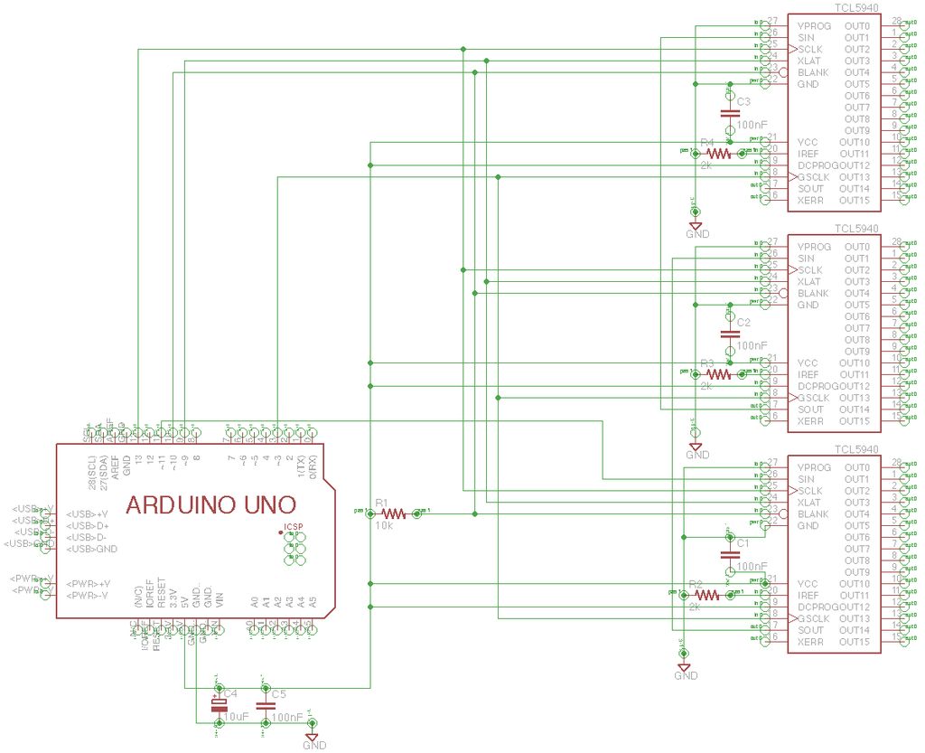
Edit the tlc_config.h file to modify the number of TLC5940’s you are using. This project runs thee TLCs so the line reads
#define NUM_TLCS 3
The code is pretty straightforward from here and is commented. I have some comments at the end too.
LEDController.ino
#include "Arduino.h"
#include <Tlc5940.h>
#include <tlc_config.h>
#include "LedController.h"

// Root List for all LEDs
List *lightList = NULL;
// various values for iterating through the RGBs
int rgbIndex = 0;
int rgbLastStart = 0;
boolean firstRGBIndex;
int maxRGB = 252;

// Handy for steping through all the LEDs
// Each LED will flash, which helps find missing or incorrect connections
void diag()
{
  for(uint8_t x= 0; x < 40; x++)
  {
    if ( x > 0)
    {
      Tlc.set(x-1,0);
    }
    Tlc.set(x,1000);
    while(Tlc.update());
    delay(500);
  }
}

/*
Pause for 5 seconds so that you can pull up
any diagnostic you may need.
Initialize the TLC chain.
Create the complete light list
*/
void setup()
{
  delay(5000);
  Tlc.init();
  Tlc.clear();
  lightList = createList();

  addNode(lightList, createRGBCluster1());
  addNode(lightList, createLEDCluster1a());
  addNode(lightList, createLEDCluster2());
}

/*
Increment the RGB value so it slowly moves through
the list of color transitions.
Keep the current time so you know when to turn on and off lights.
Run through the list.
*/
void loop()
{

  //diag();
  rgbIndex = rgbLastStart + 1;
  firstRGBIndex = true;
  long time = millis();
  iterateList(time,lightList);

  /*
  The update finishes asynchronously on the TLC's.
  You must wait till everything updates or your lights will
  display incorrect values.
  */
  while(Tlc.update());
}

/* Single link list.
Most of the following functions create a node of some type
and attach it to the end of a list. This system creates lists of lists for each
LED array. This exposed some memory challenges as the list is using some
statically allocated values and shares some of those values. Pointers
would have been a wiser choice.
*/
List* createList(void)
{
  List *list = (List*)malloc(sizeof(List));
  list->head = NULL;
  list->tail = NULL;
  return list;
}

List* addNode(List* list, Node* node)
{
 if (list != NULL && node != NULL)
 {
   if (list->head == NULL)
   {
     list->head = node;
     list->tail = list->head;
   } else {
     list->tail->next = node;
     list->tail = node;
   }
 }
}
Node* createNode(NodeType type, uint8_t pin)
{
  Node *result = (Node*)malloc(sizeof(Node));
  result->next = NULL;
  result->type = type;

  switch(type)
  {
    case LIST:
      result->value = createList();
      break;
    case LED_RGB:
      result->value = createRGB(pin);
      break;
    case LED_NORMAL:
      result->value = createLED(pin);
      break;
  }
  return result;
}

Node* createRGBNode(List* list, uint8_t pin, Runtimes runtimes, RGB *useSettings)
{
  Node *results = createNode(LED_RGB, pin);
  RGB* rgb = (RGB*)results->value;
  configureRGB(rgb, runtimes, useSettings);
  addNode(list, results);
  return results;
}

void configureRGB(RGB* rgb, Runtimes runtimes, RGB *useSettings)
{
  if ( useSettings != NULL)
  {
    rgb->useSettings = useSettings;
    rgb->color = useSettings->color;
    rgb->runtimes = useSettings->runtimes;
  } else
  {
    rgb->runtimes = runtimes;
  }
}

RGB* createRGB(uint8_t pin)
{
  RGB *result = (RGB*)malloc(sizeof(RGB));
  result->pin = pin;
  result->color.r = 0;
  result->color.g = 0;
  result->color.b = 0;
  result->useSettings = NULL;
  return result;
}

Node* createLEDNode(List* list, uint8_t pin, Runtimes runtimes, uint8_t level)
{
  Node *results = createNode(LED_NORMAL, pin);
  LED* led = (LED*)results->value;
  led->level = level;
  led->runtimes = runtimes;
  addNode(list, results);
  return results;
}

LED* createLED(uint8_t pin)
{
  LED *result = (LED*)malloc(sizeof(LED));
  result->pin = pin;
  result->level=0;
  result->runtimes.startTime=0;
  result->runtimes.runTime=0;
  result->runtimes.on=false;
  return result;
}

void setRGBLed(RGB *led)
{
  Tlc.set(led->pin,led->color.r);
  Tlc.set(led->pin+1,led->color.g);
  Tlc.set(led->pin+2,led->color.b);
}

/*
iterate through the list and determine the correct
way to execute each node.
*/
void iterateList(long time, List* list)
{
  if(list != NULL)
  {
    Node* node = list->head;
    while(node != NULL)
    {
      executeNode(time, node);
      node = node->next;
    }
  }
}

void executeNode(long time, Node* node)
{
  if(node != NULL)
  {
    switch(node->type)
    {
      case LIST:
        iterateList(time, (List*)node->value);
        break;
      case LED_RGB:
        setRGB(time,(RGB*)node->value);
        break;
      case LED_NORMAL:
        setLED(time,(LED*)node->value);
        break;
      default:
        Tlc.set(1,200);
        Tlc.update();
        break;
    }
  } else {
  }
}

/*
Horrible cheating going on here.
There is only one RGB list so we're going to keep some extra state
and apply it to just this rgb list. blech.
However, this array runs much faster by iterating through precalculated
values than trying to calculate and display those values.
*/
void setRGB(long time, RGB* rgb)
{
  if (rgb != NULL)
  {
    boolean cycle = time > rgb->runtimes.startTime + rgb->runtimes.wait;
    if ( cycle )
    {
      if ( rgb->useSettings != NULL )
      {
        rgb->color = rgb->useSettings->color;
        rgb->runtimes = rgb->useSettings->runtimes;
      } else
      {
        if ( firstRGBIndex )
        {
          firstRGBIndex = false;
          rgbLastStart++;
          if ( rgbLastStart > maxRGB)
          {
            rgbLastStart = 0;
          }

          rgbIndex = rgbLastStart;
        }
        rgb->color = rgbPattern[rgbIndex++];

        if ( rgbIndex > maxRGB)
        {
          rgbIndex = 0;
        }

      }
      rgb->runtimes.startTime = time;
    }
    setRGBLed(rgb);

  }
}

void setLED(long time, LED* led)
{
  if (led != NULL)
  {
    long execWindow = led->runtimes.startTime + led->runtimes.runTime;
    if(led->runtimes.runTime == -1 || (time > led->runtimes.startTime && time < execWindow))
    {
      led->runtimes.on = true;
      Tlc.set(led->pin, led->level);
    } else  if ( time > execWindow && led->runtimes.on == true ) {
      led->runtimes.startTime = time + led->runtimes.wait;
      led->runtimes.on = false;
      Tlc.set(led->pin, 0);
    }
  }
}

/*
The various LED array factory methods
*/
Node* createRGBCluster1(void)
{
  int i = 0;
  int wait = 50;
  Runtimes rt = (Runtimes) { 0, 0, wait, false };

  Node* rgbList = createNode(LIST, 0);
  List* rgbCluster1 = (List*)rgbList->value;
  Node* a = createRGBNode( rgbCluster1, i, rt, NULL);
  Node* b = createRGBNode( rgbCluster1, i+=3, rt, NULL);
  Node* c = createRGBNode( rgbCluster1, i+=3, rt, NULL);
  Node* d = createRGBNode( rgbCluster1, i+=3, rt, NULL);
  Node* e = createRGBNode( rgbCluster1, i+=3, rt, NULL);

  // Let them share values which creates a kind of cool looking
  // fountain effect.
  createRGBNode( rgbCluster1, i+=3, rt, (RGB*)e->value);
  createRGBNode( rgbCluster1, i+=3, rt, (RGB*)d->value);
  createRGBNode( rgbCluster1, i+=3, rt, (RGB*)c->value);
  createRGBNode( rgbCluster1, i+=3, rt, (RGB*)b->value);
  createRGBNode( rgbCluster1, i+=3, rt, (RGB*)a->value);

  return rgbList;
}

Node* createLEDCluster1a(void)
{
  int i = 30;
  Node* ledList = createNode(LIST, 0);
  List* ledCluster = (List*)ledList->value;
  createLEDNode( ledCluster, i++, (Runtimes) { -1, -1, -1, true }, 300);
  createLEDNode( ledCluster, i++, (Runtimes) { -1, -1, -1, true }, 300);
  createLEDNode( ledCluster, i++, (Runtimes) { -1, -1, -1, true }, 300);
  createLEDNode( ledCluster, i++, (Runtimes) { -1, -1, -1, true }, 300);
  createLEDNode( ledCluster, i++, (Runtimes) { -1, -1, -1, true }, 300);
  createLEDNode( ledCluster, i++, (Runtimes) { -1, -1, -1, true }, 300);
  return ledList;
}

Node* createLEDCluster2(void)
{
  int i = 36;

  Node* ledList = createNode(LIST, 0);
  List* ledCluster = (List*)ledList->value;
  createLEDNode( ledCluster, i++, (Runtimes) { 10000, 30000, 25000, true }, 3000);
  createLEDNode( ledCluster, i++, (Runtimes) { 10000, 30000, 25000, true }, 3000);
  createLEDNode( ledCluster, i++, (Runtimes) { 3000, 90000, 45000, true }, 3000);
  createLEDNode( ledCluster, i++, (Runtimes) { 3000, 90000, 45000, true }, 3000);

  return ledList;
}

/*
This is some old code that did the sine wave calculation.
It works but is very slow. I wrote some code to capture the values
and write them out the serial console instead and then copied the values
into the header

void setRGBFreq(RGB *led, uint8_t i, uint8_t max)
{
    float frequency = .3;
    led->r = sin(frequency*(i) + 0) * 127 + 128;
    led->g = sin(frequency*(i) + 2) * 127 + 128;
    led->b = sin(frequency*(i) + 4) * 127 + 128;

    uint8_t total = led->r + led->g + led->b;
    if ( total > max )
    {
      led->r -= led->r/total * 100.0;
      led->g -= led->g/total * 100.0;
      led->b -= led->b/total * 100.0;
    }
    //printList(led);
}*/
For more detail: Creative diorama lighting with the Arduino and TLC5940
- What is the main goal of this project?
To create realistic, scripted lighting for model buildings using an Arduino and TLC5940 drivers. - Which LED drivers are used in the project?
The project uses TLC5940NT LED drivers. - What types of LEDs are recommended?
Wide-angle white Straw Hat IL336 LEDs and diffused RGB IL614 5mm common anode LEDs are recommended. - How does the code create RGB color transitions?
RGB transitions use a precalculated sine-wave pattern stored in an array for speed and smooth color changes. - How are LEDs organized in the code?
LEDs are organized into clusters and lists; clusters represent RGB groups or sets of windows with start and end times for actions. - What should be done to prevent light bleed between windows?
Wrap each LED in a light-tight paper box, cover with foam, paint or glue foam around windows, and test with a bright flashlight to find leaks. - How many TLC5940 chips does the example project use?
The example project runs three TLC5940 chips (NUM_TLCS set to 3). - How do you install the TLC5940 Arduino library per the article?
Download and unzip the library, then in the Arduino editor use Sketch -> Import Library and add the library. - What precautions are advised about LED brightness?
Set brightness low initially because TLC5940 steps go up to 4096; overly bright settings can be painful to the eyes and should be increased later to compensate for diffusion. - What tools are helpful for soldering and assembly?
Tools include a soldering iron with temperature control, multimeter, wire strippers, needle-nose pliers, calipers, model files, wire cutters, and vices or circuit board holders.