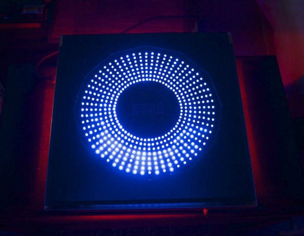
If you can’t see the original video in your country please try this other link of a “music edited version”:
Step 1: Bill of Material (All you will need)
For the Housing
- Three 300x300mm x 3mm thickness Acrylic glass (black)
- One 300x300mm x 3mm thickness Acrylic glass (transparent)
- Acrylic glass adhesive and polish
- Twenty 15mm spacers M3 thread
- Twenty M3 screws + washers
- One 300×300 picture frame
For the Electronic
- 480 3mm LEDs (color of your choice)
- Sixty 120 Ω resistors
- One 4-Digit 7-Segment Display common anode
- Eight 74HC595 Shift Registers
- Eight BD139 NPN Transistors
- One Arduino ATMEGA 2560 Board
- One TLC5940
- 1m RGB-LED-Strip
- One LM317 voltage regulator
- One 0.1μF capacitor
- One 1μF capacitor
- One 1 kΩ resistor
- One 330 Ω resistor
- One 2.5 mm DC Jack
- Ribbon Cable
- Header Strips
- One I2C RTC DS1307 AT24C32 Real Time Clock Module For Arduino Mega2560
- Lot of Copper Wire and tin solder
- Eight 750 Ohm Resistors
- Four circuit strip boards
- One 12V 1A Powersupply or one 11,1 1000-2000mAh Lipo rechargeable battery
Step 2: Building the housing (Part1)
- Cut and drill the 3mm acrylic plates as shown in the sketch
- Glue front housing plate (black plate), bonding part (transparent plate) and LEDs slice plate (black plate) together
For more detail: LED – Mega Clock Using Arduino

